Example Program #3: Blink
Here we will look at a program that will blink an LED at 1 Hz. The program is written assuming an ATmega328P microcontroller running at 16 MHz with an LED connected to PINB0. If your setup is different you will have to make adjustments.
In this program we will see how conditional branching works and use it to set up a 0.5 second delay loop. We will also look at execution times for individual instructions and see how to calculate exactly how long a segment of code will take to run. The program is shown below.
	.include "m328pdef.inc"

	.def	mask 	= r16		; mask register
	.def	ledR 	= r17		; led register
	.def	oLoopR 	= r18		; outer loop register
	.def	iLoopRl = r24		; inner loop register low
	.def	iLoopRh = r25		; inner loop register high

	.equ	oVal 	= 71		; outer loop value
	.equ	iVal 	= 28168		; inner loop value

	.cseg
	.org	0x00
	clr	ledR			; clear led register
	ldi	mask,(1<<PINB0)		; load 00000001 into mask register
	out	DDRB,mask		; set PINB0 to output

start:	eor	ledR,mask		; toggle PINB0 in led register
	out	PORTB,ledR		; write led register to PORTB

	ldi	oLoopR,oVal		; initialize outer loop count

oLoop:	ldi	iLoopRl,LOW(iVal)	; intialize inner loop count in inner
	ldi	iLoopRh,HIGH(iVal)	; loop high and low registers

iLoop:	sbiw	iLoopRl,1		; decrement inner loop registers
	brne	iLoop			; branch to iLoop if iLoop registers != 0

	dec	oLoopR			; decrement outer loop register
	brne	oLoop			; branch to oLoop if outer loop register != 0

	rjmp	start			; jump back to start
Code Breakdown
In this program we start off just as we always do, with an directive for our pin and register definitions.
.include "m328pdef.inc"After this, we use the directive to give some of our registers meaningful names.
	.def    mask    = r16           ; mask register
        .def    ledR    = r17           ; led register
        .def    oLoopR  = r18           ; outer loop register
        .def    iLoopRl = r24           ; inner loop register low
        .def    iLoopRh = r25           ; inner loop register high
For our program, we define a mask register to control LED toggling, a register to hold the value we are going to write to our LED port, a register to act as a counter for an outer loop, and a pair of registers to act as counter for an inner loop. We could just use the register's names, but defining them makes our program easier to read and easier to change register later if we need to.
Now we get to a new directive - equals. The directive lets us define constants in our program just like in C. As with the directive, using gives meaningful names to the constants in our program and makes it easy to change the value later if we need to.
	.equ    oVal    = 71            ; outer loop value
        .equ    iVal    = 28168         ; inner loop value
Above we define two constants oVal and iVal to hold initial values for the delay loops we will use later.
Use the directive to give meaningful names to constants.
As we should always do, we specify code segment at the beginning of flash so our program executes immediately when the microcontroller starts.
	.cseg
        .org    0x00
For our first instruction, we clear the previously defined ledR register to ensure its contents are 0. We then load mask with the value (1<<PINB0). The contents of mask are written to DDRB so that PINB0 is set as an output.
	clr	ledR			; clear led register
        ldi     mask,(1<<PINB0)		; load 00000001 into mask register
        out     DDRB,mask		; set PINB0 to output
LED Toggling
Next we have the label which will mark the beginning of the LED toggling delay loop. We begin by performing an exclusive OR between ledR and mask. Remember that ledR has the value 00000000 when we first enter the loop and mask has the value 00000001, so when the exclusive OR is finished ledR will contain the value 00000001.
start:	eor	ledR,mask		; toggle PINB0 in ledR
	out	PORTB,ledR		; write ledR to PORTB
The next time the loop executes ledR will contain the value 00000001 and the value of mask will still be 00000001. Thus, when the exclusive OR is executed again ledR will contain the value 00000000. This is our way of toggling the bit. We output this value to PORTB to will switch PINB0 on or off.
We have a way to toggle PINB0, now we just need a way to waste some time to create a delay. We will do this with two loops, an inner and outer, each of which will decrement the value of a particular register until it reaches zero.
Delay Loop
The value for our outer loop counter will be 8-bits and is loaded into the register oLoopR. We will load the constant oVal (defined as 71) into our outer loop counter register.
ldi oLoopR,oVal ; initialize outer loop countTwo 8-bit counters simply won't buy us enough time for a noticeable delay at 16 MHz, so we will need a 16-bit value for our inner loop. For this we will use the registers r24 and r25 (defined as iLoopL and iLoopH respectively) since they support some special 16-bit instructions.
At the label oLoop (outerloop), we initialize oLoopRl and oLoopH using two separate ldi instructions, as there is no way to directly load a 16-bit value to two registers with a single instruction.
To make our lives easier, the assembler offers a few functions to break a number into its constituent bytes - LOW() and HIGH(). The following shows how to use LOW() and HIGH() to break iVal into its lower and upper bytes and store them in our inner loop counting registers.
oLoop:	ldi	iLoopRl,LOW(iVal)	; intialize inner loop count in inner
	ldi	iLoopRh,HIGH(iVal)	; loop high and low registers
Note: The functions and break 16-bit numbers into their lower and higher bytes, respectively. This is done by the assembler, not the microcontroller.
We have initialized our 16-bit counter before entering our inner loop, now it is time to write the code for the inner loop. We start by marking it with the label .
We then use the 16-bit instruction sbiw to decrement the registers iLoopRl and iLoopRh. sbiw is called with the operand iLoopRl (iLoopRh is implied) and the constant 1. In each cycle of the loop we will be subtracting 1 from iLoopRl and iLoopRh and the microcontroller will automatically handle carry bits between the two registers.
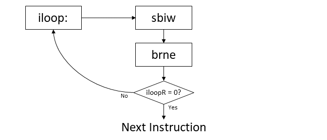
iLoop: sbiw iLoopRl,1 ; decrement iLoopRh:iLoopRlWe now have a way to decrement our 16-bit counter, but nothing we have seen so far allows us to loop until it reaches zero and continue on when it does. What we introduce now is a conditional branch.
The instruction brne - branch if not equal - tests if the result of the previous operation was zero. If it was not, brne will branch to the label given as an operand. If it was zero brne will continue to the next instruction.
iLoop:	sbiw	iLoopRl,1		; decrement iLoopRh:iLoopRl
	brne	iLoop			; branch to iLoop if iLoopRh:iLoopRl != 0
Immediately before the brne instruction we decremented iLoopRl:iLoopRh. If the count has not reached zero, we need to keep decrementing, so we supply the label as the target for brne.
The code will continue to decrement iLoopRl:iLoopRh and branch back to while it's not zero. When iLoopRl:iLoopRh finally does reach zero, brne will move on to the next instruction.
This flow is shown in the following diagram.
Now that we have an inner loop which will decrement our 16-bit counter, we just need to do the same for our outer loop counter. Since it is only 8-bits, we can use the instruction dec to decrement its count. We can then use the same conditional branch instruction brne to test if it's zero or not.
	dec     oLoopR                  ; decrement oLoopR
	brne    oLoop                   ; branch to oLoop if oLoopR != 0
This time we don't want to just jump back to the dec instruction though - if oLoopR is not zero, we want to reinitialize our 16-bit counter and go through that loop all over again so we provide the label . Our code will now go through our inner loop each time it goes through the outer loop giving us a full 24-bit counter - and enough wasted time to have a noticeable delay.
When the outer loop counter oLoopR finally reaches zero we will continue to our next instruction - a jump back to the start where we will toggle our output pin and start the whole process all over again. The entire "delay section" of our code is shown below.
	ldi	oLoopR,oVal		; initialize outer loop count

oLoop:	ldi	iLoopRl,LOW(iVal)	; intialize inner loop count in inner
	ldi	iLoopRh,HIGH(iVal)	; loop high and low registers

iLoop:	sbiw	iLoopRl,1		; decrement iLoopRh:iLoopRl
	brne	iLoop			; branch to iLoop if iLoopRh:iLoopRl != 0

	dec	oLoopR			; decrement oLoopR
	brne	oLoop			; branch to oLoop if oLoopR != 0

	rjmp	start			; jump back to start
Calculating Delay Time
Now that you've seen the program, you may be wondering where the loop values oVal and iVal came from.
If you consult the ATmel Instruction Set, you will see that each instruction executes in a precise number of clock cycles. Most instructions take only one or two, but some can take three or four. Since we know how long each instruction takes and the CPU frequency of our microcontroller, we can calculate exactly how long our code will take to run - something that is not possible in C.
Let's start by taking a look at the inner loop. We have two instructions - sbiw and brne.
iLoop:	sbiw	iLoopRl,1
	brne	iLoop
If you take a look at the ATmel instruction set, you will see that sbiw takes 2 clock cycles to execute. However, if you look at the cycles for brne, it gives a slightly more complicated answer: 1 if condition is false, 2 if condition is true.
If you look at the loop, you will notice that the brne condition evalutes true whenever iLoopRl is not zero. So brne will take 2 cycles everytime we go through the loop, except for the last time.
The time for this loop is actually easy to calculate. We will go through the loop iVal times. Each sbiw instruction will take 2 clock cycles and the brne instruction will take 2 cycles eveytime except for the last iteration, which will only take 1. Thus, it will take iVal*(2+2)-1 = 28168*(2+2)-1 = 112671 cycles to fully complete the inner loop.
iLoop:	sbiw	iLoopRl,1		; 2 cycles
	brne	iLoop			; 2 or 1 cycles
The inner loop is embedded in the outer loop so we must include its cycle count when calculating the time for our outer loop. Lets take a look at the cycles for the instructions in the outer loop.
oLoop:	ldi	iLoopRl,LOW(iVal)	; 1 cycle
	ldi	iLoopRh,HIGH(iVal)	; 1 cycle
					;
iLoop:	sbiw	iLoopRl,1		; 112671 cycles
	brne	iLoop			;
					;
	dec	oLoopR			; 1 cycle
	brne	oLoop			; 2 or 1 cycles
Add all of these up and you will see that each iteration of the outer loop takes either 112676 or 112675 cycles, depending on whether the final brne instruction evaluates true or false.
We are using oLoopR as the counter for our outer loop, which is initialized with the constant oVal. We can calculate the total number of cycles for our outer loop to run the same way we did for the inner loop: oVal*112676-1 = 71*112676-1 = 7999995 cycles.
We have just a few more instructions in our total loop to complete the program:
start:  eor     ledR,mask               ; 1 cycle
        out     PORTB,ledR              ; 1 cycle

        ldi     oLoopR,oVal             ; 1 cycle

oLoop:  ldi     iLoopRl,LOW(iVal)	;
        ldi     iLoopRh,HIGH(iVal)      ;
					;
iLoop:  sbiw    iLoopRl,1               ; 799995 cycles
        brne    iLoop                   ;
					;
        dec     oLoopR                  ;
        brne    oLoop                   ;

        rjmp    start                   ; 2 cycles
Adding the rest of these instructions to our total gives a cycle count of 8000000. At 16 MHz, this is exactly 0.5 seconds!
Ok, we've see how to calculate execution time given counter values, but how do we get counter values for a desired cycle count? We just need to do the same analysis as before, but keep the counter values as variables in the equation and solve for them at the end.
For the inner loop, our execution time is
innerLoopCount	= iVal*(2+2)-1
		= 4*iVal-1
For the outer loop
outerLoopCount	= oVal*(1+1+innerLoopCount+1+2)-1
		= oVal*(5+innerLoopCount)-1
		= oVal*(5+(4*iVal-1))-1
		= oVal*(4+4*iVal)-1
		= 4*oVal*(1+iVal)-1
Adding in the rest of the instructions we get
total		= 1+1+1+outerLoopCount+2
		= 5+outerLoopCount
		= 5+4*oVal*(1+iVal)-1
		= 4+4*oVal*(1+iVal)
We now have a slight problem. We have two variables, oVal and iVal, but only one equation, so we can't solve for both.
A quick and easy method to get around this is to just pick a value for one of the counters and solve for the necessary value of the other. We could say, pick a value of 255 for oVal, then rearrange and solve for the value of iVal that will give 8000000 cycles.
8000000		= 4+4*255*(1+iVal)
8000000-4	= 1020*(1+iVal)
7999996/1020	= 1+iVal

iVal		= 7842.13
That's great but we can only work with integers. iVal must be rounded to the nearest whole number which will give us a slight error. Plugging 7842 back into our equation for clock cycles, we get 7999864, which has an error of 0.0017%. Terrible approximation, right?
If you really want an exact number of clock cycles, here's what I suggest you do. Open a spreadsheet and place all the possible values for one of your counter values down one column. In another column, calculate the corresponding value for your other counter and find the minimum value. Hopefully it's zero, but if not you will have to live with the closest approximation or add some dummy instructions to your loop until the math works out to an integer number. An example of such a spreadsheet is shown below.
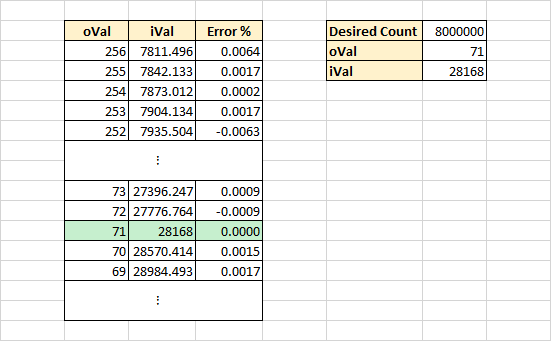
You may notice the oVal count begins at 256. 8-bit numbers only go to 255, why include this value?
Think for second what would happen if we initialized oVal with the number 0? Since we decrement it before we check it with brne, it will actually underflow in the first iteration of the loop (i.e. it will wrap back to 255). Therefore, initializing the counter to 0 will give 256 counts.
This neat little trick buys you an extra loop value should you need it. Keep in mind though this only works if you are decrementing your count before you check its value.
Conclusion
There you have it - a program that blinks an LED at 1 Hz. We've seen many useful new features in this tutorial, most notably conditional branches. In the following tutorials we will look at all the possibilities offered by conditional branching and the driving force behind them, the Status Register.