ATmega32U4 TQFP Breakout Board
Since ATmega32U4s are not available in DIP format, I had not used them in any of my breadboard projects. However, I decided that a simple breakout board would
- Provide ISP connections to ensure I could actually write programs to the microcontroller
- Provide UART output for debugging purposes
- Ensure these 16 MHz SMD crystals worked as expected
- Ensure these SMD tactile switches worked as expected
- Include an LED on PINB0 so I could run Blink!
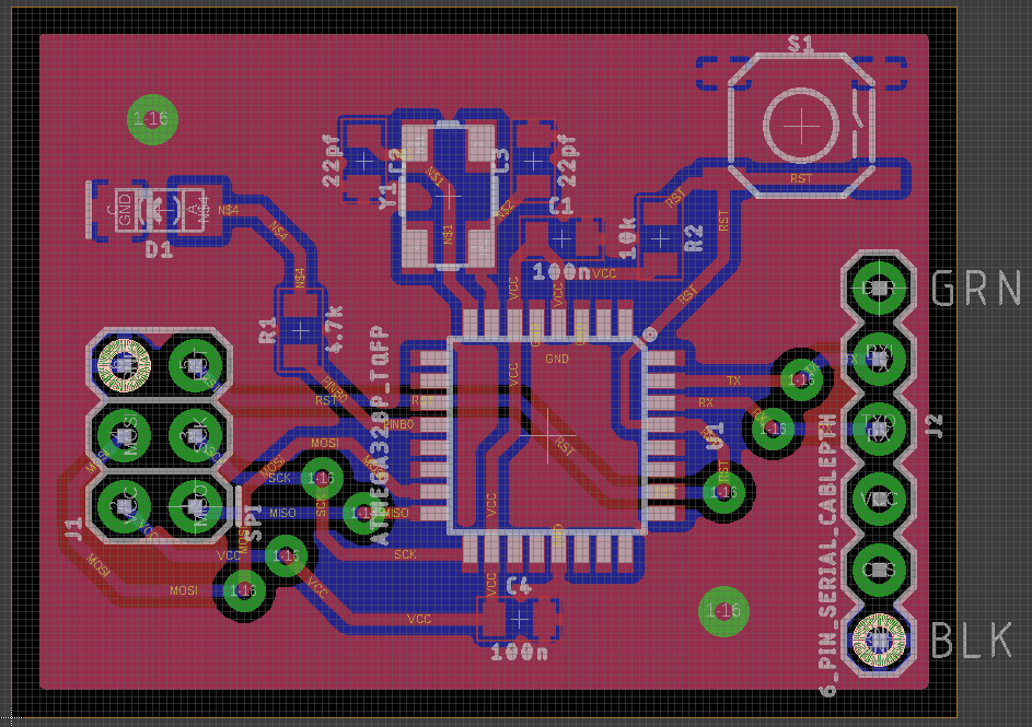
Below is the design I came up with to fit these goals. Download the Eagle files here. (Note: you will need to download the Sparkfun library to view correctly). This is a very minimalist board - it provides no breakout for any pins except for UART tx/rx and needs to be connected to an ISP programmer for power. However, it meets all of my design goals - and nothing more!
Board
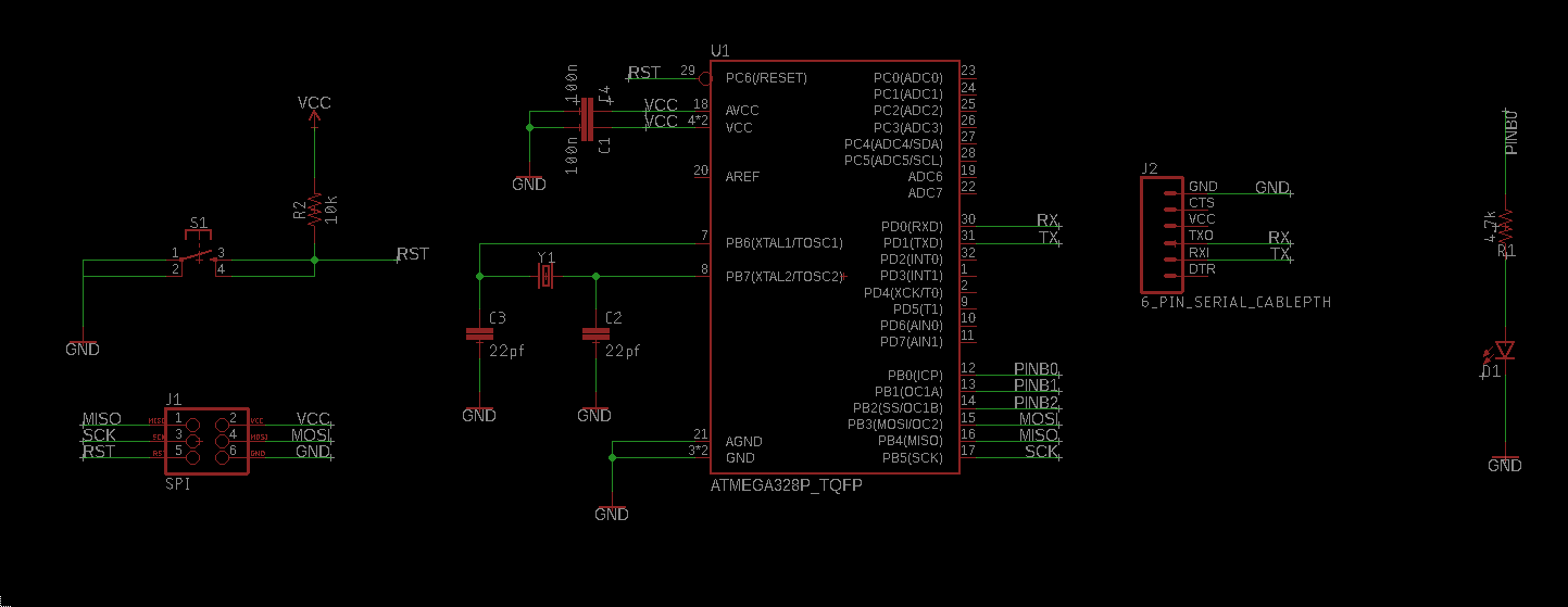
Schematic
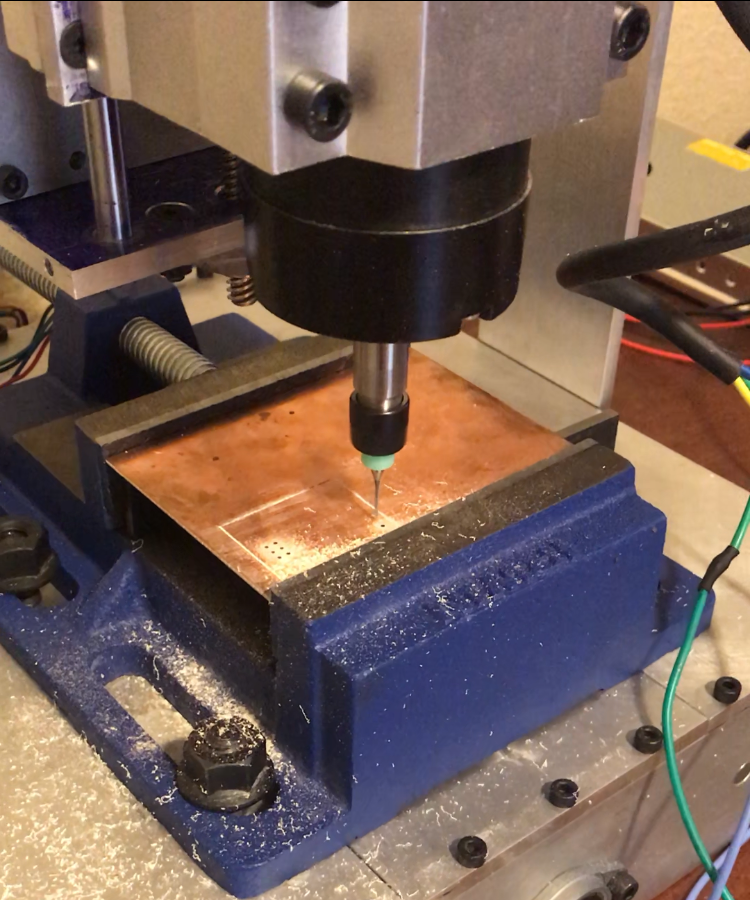
Building
Unfortunately I did not think to take too many pictures while etching this board, but here it is being drilled.
Finished Product
Below is the homemade board after drilling, etching, masking and soldering.
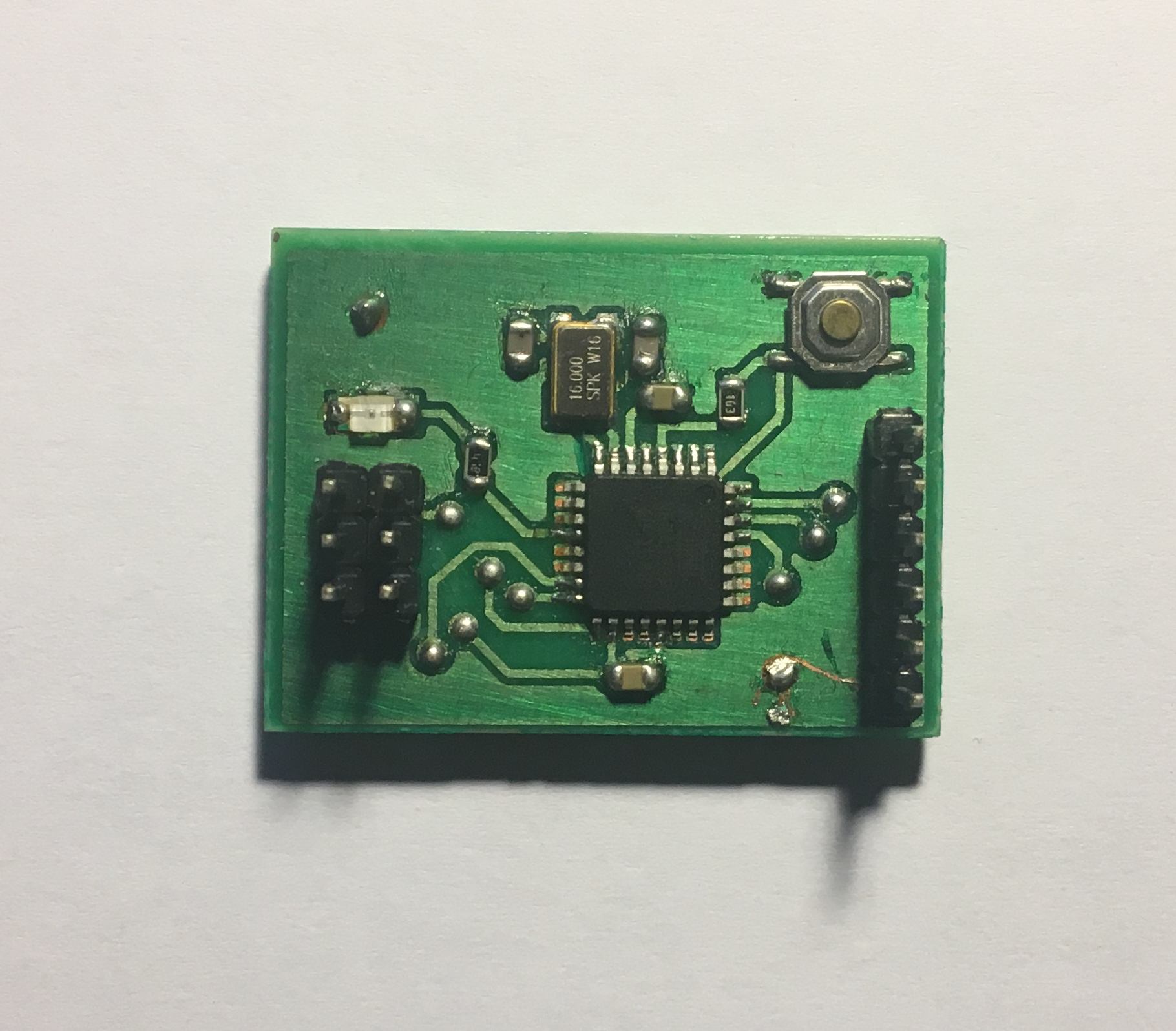
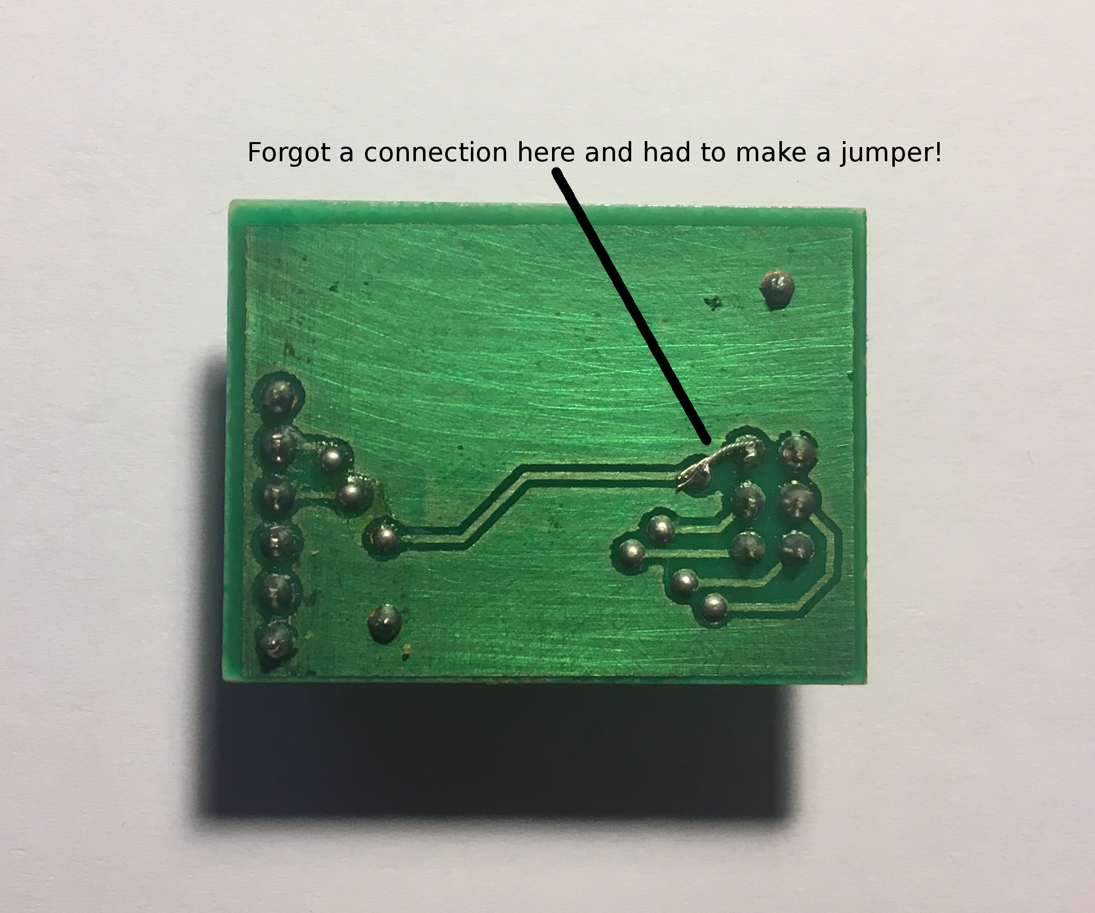
In the end the board turned out very well. Everything worked as expected - my usbtiny programmer was able to communicate with the microcontroller, the external oscillator worked as proved by running an LED blink program and the UART outputs were correctly read by my computer.
Unfortunately, as seen in the bottom side of the board, I had to solder a jumper wire between one of the ISP pins and a via. This error was not caught in Eagle as it is assumed holes are through-plated, which is something I cannot do with my homemade boards. Luckily it was easily fixable and is something to keep my eyes out for in future designs.