Interfacing an SD Card Part 4
In the previous tutorial, we completed the initialization process for an SD card. Here we will look at reading and writing data to the SD card.
Block Length
Read and write operations are performed on SD cards in blocks of set lengths. Block length can be set in Standard Capacity SD cards using CMD16 (SET_BLOCKLEN). In this tutorial, we will only consider SDHC and SDXC cards, where the block length is always set to 512 bytes.
Single Block Read
The command for a single block read is CMD17 - READ_SINGLE_BLOCK. Its format is shown in the table below.
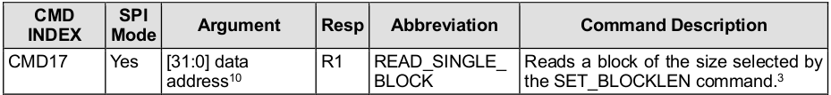
Note that we need to provide the address we want to read from in the argument. SDHC and SDXC are block addressed, meaning an address of 0 will read back bytes 0-511, address 1 will read back 512-1023, etc. With 32 bits to specify a 512 byte block, the maximum size a card can support is (2^32)*512 = 2048 megabytes or 2 terabytes.
The flow of a single block read is shown in the diagram below:
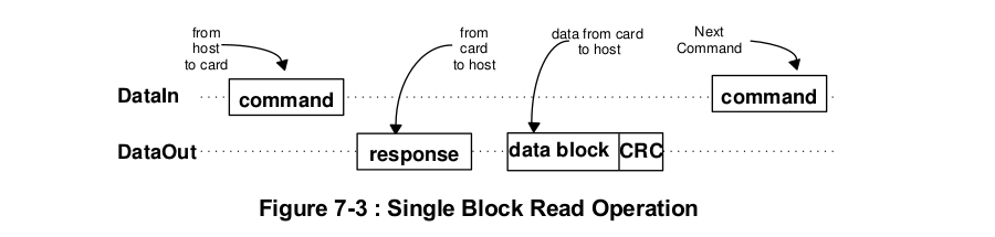
When CMD17 is sent, the card will respond with R1, followed by a data block suffixed with a CRC. The card may take some time between sending its R1 response and its first data byte, so how do we know when the data is actually starting? Single data blocks are always preceded by the bits 0b11111110 (0xFE), which is referred to as a start token.
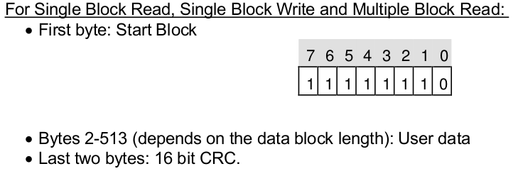
Immediately after sending the start token the card will send out a data block length of data (which is always 512 bytes for SDHC and SDXC cards). This is then followed by a 16-bit CRC.
Writing a Read Block Function
Here is a function that allows us to read a single block from an SD card.
#define CMD17                   17
#define CMD17_CRC               0x00
#define SD_MAX_READ_ATTEMPTS    1563

/*******************************************************************************
 Read single 512 byte block
 token = 0xFE - Successful read
 token = 0x0X - Data error
 token = 0xFF - Timeout
*******************************************************************************/
uint8_t SD_readSingleBlock(uint32_t addr, uint8_t *buf, uint8_t *token)
{
    uint8_t res1, read;
    uint16_t readAttempts;

    // set token to none
    *token = 0xFF;

    // assert chip select
    SPI_transfer(0xFF);
    CS_ENABLE();
    SPI_transfer(0xFF);

    // send CMD17
    SD_command(CMD17, addr, CMD17_CRC);

    // read R1
    res1 = SD_readRes1();

    // if response received from card
    if(res1 != 0xFF)
    {
        // wait for a response token (timeout = 100ms)
        readAttempts = 0;
        while(++readAttempts != SD_MAX_READ_ATTEMPTS)
            if((read = SPI_transfer(0xFF)) != 0xFF) break;

        // if response token is 0xFE
        if(read == 0xFE)
        {
            // read 512 byte block
            for(uint16_t i = 0; i < 512; i++) *buf++ = SPI_transfer(0xFF);

            // read 16-bit CRC
            SPI_transfer(0xFF);
            SPI_transfer(0xFF);
        }

        // set token to card response
        *token = read;
    }

    // deassert chip select
    SPI_transfer(0xFF);
    CS_DISABLE();
    SPI_transfer(0xFF);

    return res1;
}
Note here that our function takes a 32-bit address as an argument and requires a buffer of at least 512 bytes to store the data in. We also pass a pointer to an 8 bit value that will be used to store the data token.
After we have read R1, if it is not empty (i.e. the card actually responded to the command), we poll the card until we receive a token or we timeout.
    // if response received from card
    if(res1 != 0xFF)
    {
        // wait for a response token (timeout = 100ms)
        readAttempts = 0;
        while(++readAttempts != SD_MAX_READ_ATTEMPTS)
            if((read = SPI_transfer(0xFF)) != 0xFF) break;
Per section 4.6.2.1 of the physical spec:
The host should use 100ms timeout (minimum) for single and multiple read operations
In this example, I am using a 16MHz oscillator and have the SPI clock set to divide by 128. Thus, to get the number of bytes we need to send over SPI to reach 100ms, we do (0.1s * 16000000 MHz)/(128 * 8 bytes) = 1563.
If we have received a start token, we simply read 512 bytes into our buffer, followed by the 16-bit CRC (which we will not use for now).
        // if response token is 0xFE
        if(read == 0xFE)
        {
            // read 512 byte block
            for(uint16_t i = 0; i < 512; i++) *buf++ = SPI_transfer(0xFF);

            // read 16-bit CRC
            SPI_transfer(0xFF);
            SPI_transfer(0xFF);
        }
If we do not receive a start token, we will not try to read a block from the card. If our token is 0xFF, then we never received anything from the card (and thus timed out). Otherwise, we (should) have received an error token (more on that later).
Testing it out
Using the intialization code from the previous tutorial, lets try reading the very first block from the card.
int main(void)
{
    // array to hold responses
    uint8_t res[5], sdBuf[512], token;

    // initialize UART
    UART_init();

    // initialize SPI
    SPI_init();

    // initialize sd card
    if(SD_init() != SD_SUCCESS)
    {
        UART_pputs("Error initializaing SD CARD\r\n"); while(1);
    }
    else
    {
        UART_pputs("SD Card initialized\r\n");
    }

    // read sector 0
    res[0] = SD_readSingleBlock(0x00000000, sdBuf, &token);

    // print response
    if(SD_R1_NO_ERROR(res[0]) && (token == 0xFE))
    {
        for(uint16_t i = 0; i < 512; i++) UART_puthex8(sdBuf[i]);
        UART_puts("\r\n");
    }
    else
    {
        UART_pputs("Error reading sector\r\n");
    }

    while(1) ;
}
Running this gives the following UART output on my card:
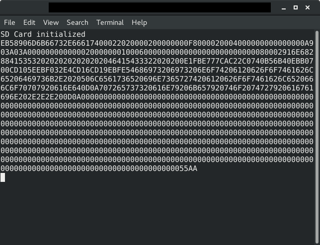
Notice that the last two bytes are 0x55 and 0xAA. This is the boot signature at the end of the Master Boot Record (MBR). If you have formatted your SD card on a PC before reading it there is a good chance you will see that same two bytes at the end of your first data block as well.
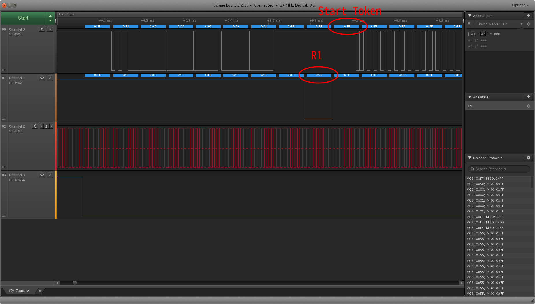
Checking the output with a logic analyzer, here is what the transition from R1 to transmitting the data block looks like:
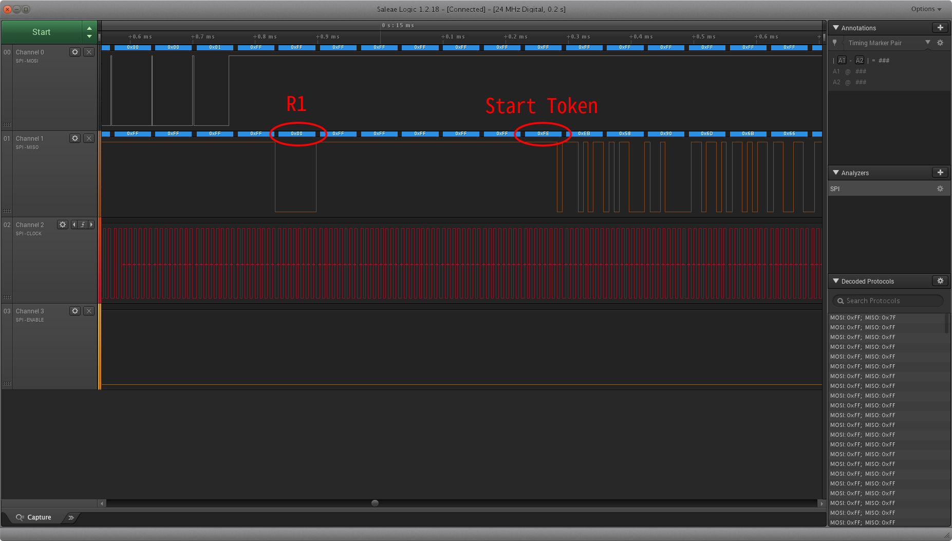
Notice that this card idled for 5 bytes before sending the start token. If we did not have a start token we would not be able to differentiate between the card idling and data that was all 1s.
Read Errors
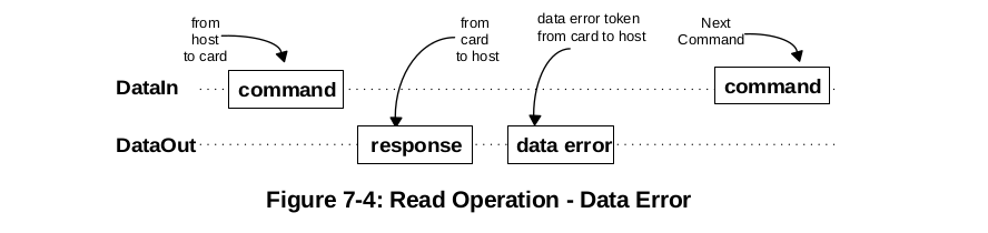
When the card is unable to retrieve the requested data, it will send a data error token instead of a data start token. This flow is shown in the diagram below.
Data error tokens have the format shown below.
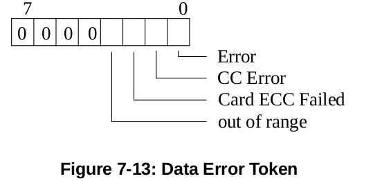
Let's take a look at a situation that will cause a data retrieval error. First a function to print the error token:
#define SD_TOKEN_OOR(X)     X & 0b00001000
#define SD_TOKEN_CECC(X)    X & 0b00000100
#define SD_TOKEN_CC(X)      X & 0b00000010
#define SD_TOKEN_ERROR(X)   X & 0b00000001

void SD_printDataErrToken(uint8_t token)
{
    if(SD_TOKEN_OOR(token))
        UART_pputs("\tData out of range\r\n");
    if(SD_TOKEN_CECC(token))
        UART_pputs("\tCard ECC failed\r\n");
    if(SD_TOKEN_CC(token))
        UART_pputs("\tCC Error\r\n");
    if(SD_TOKEN_ERROR(token))
        UART_pputs("\tError\r\n");
}
If we try to access a memory location that is out of range for the card, we will (probably) receive an error token rather than a data token. Let's try accessing memory address 0xFFFFFFFF. Unless you have a 2TB card, this should cause an error.
    uint8_t res, token;
    res = SD_readSingleBlock(0xffffffff, buf, &token);

    UART_pputs("Response 1:\r\n")
    SD_printR1(res);

    // if error token received
    if(!(token & 0xF0))
    {
        UART_pputs("Error token:\r\n");
        SD_printDataErrToken(error);
    }
    else if(token == 0xFF)
    {
        UART_pputs("Timeout\r\n");
    }
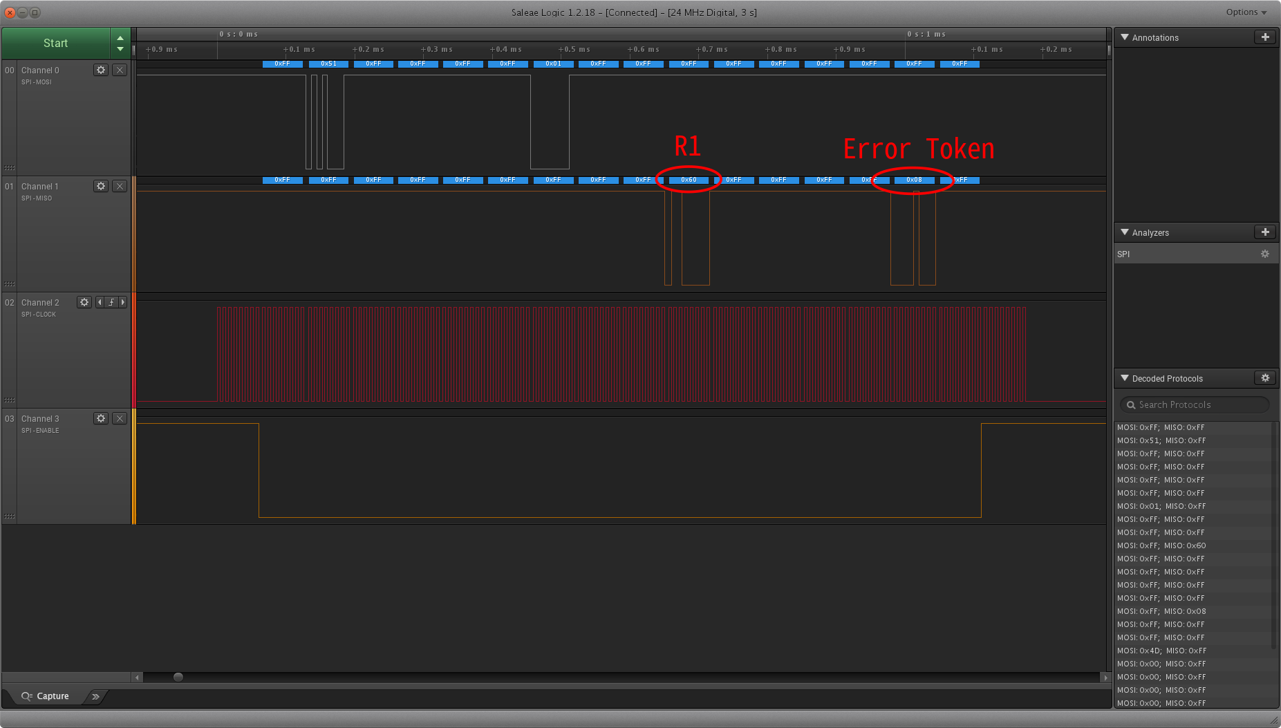
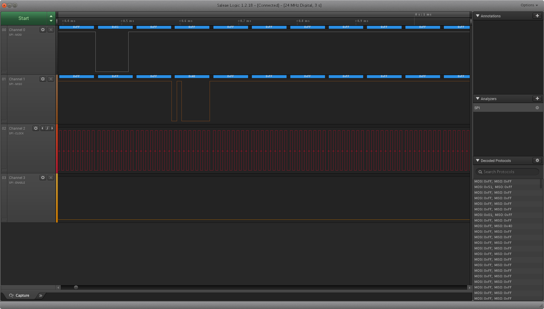
Here is what we get from the logic analyzer.
And here is what is output through UART.
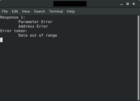
We see that R1 indicates we have a parameter error and an address error, and the error token specifies that the data is out of range.
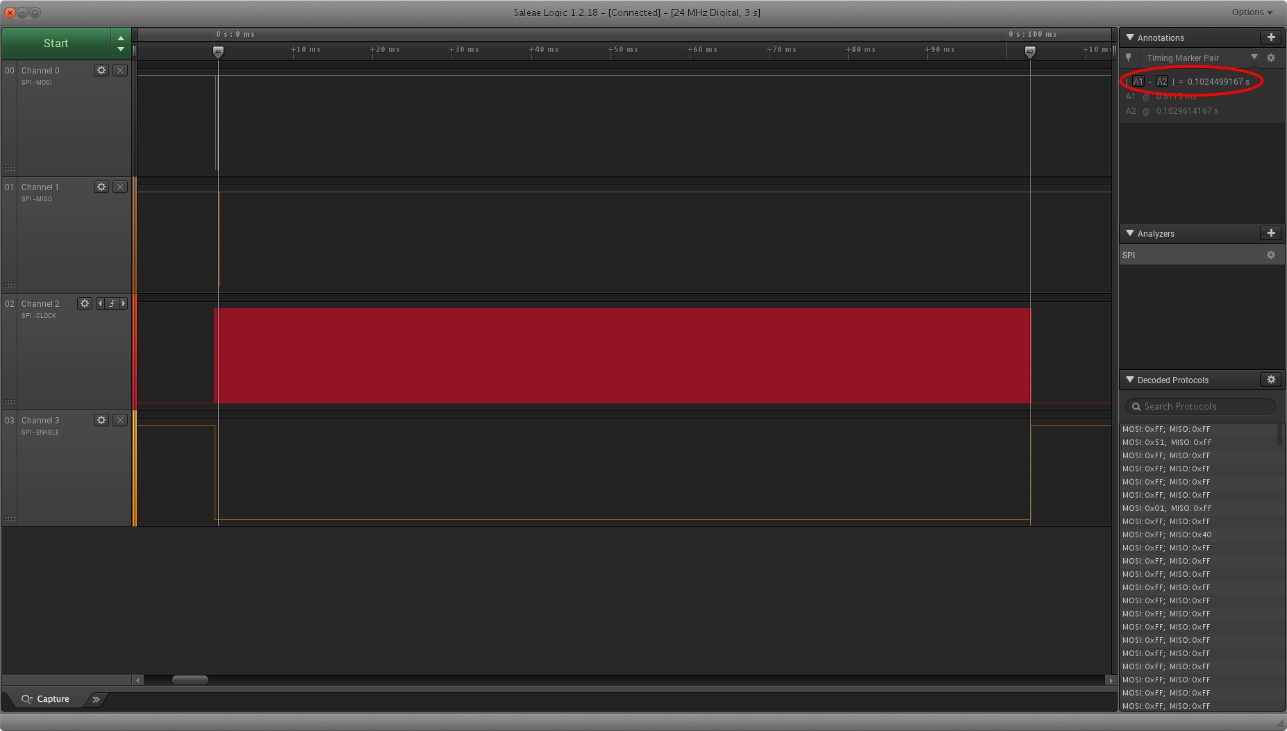
Note this behavior is not entirely consitent across cards. The previous trace is from a SanDisk card. When I run the same example on a Samsung card, this is what I get:
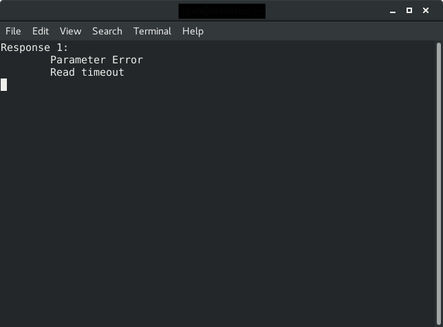
For this card, we never received an error token. Instead we timed out after ~100ms.
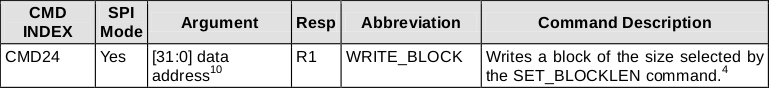
Writing Blocks
Writing, just like reading, is done in blocks of 512 bytes. The command we will be looking at here is CMD24 - WRITE_BLOCK. The format for this command is shown below.
The flow for a single block write is shown below.
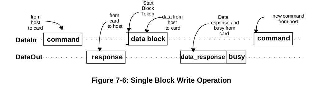
Notice that we send the write block command, wait for a response (R1), then send a start block token (0xFE) followed by 512 bytes of data to be written. After this we will wait for new type of token from the card: a data response token. The format for this is shown below.
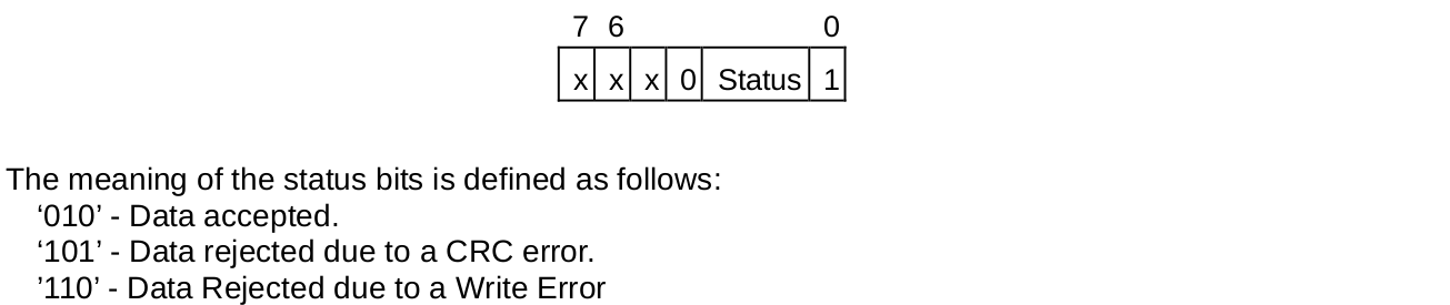
If the card accepts the data, we will get the token 0bxxx00101. The card will then send busy tokens (0x00) until it has finished writing the data.
Putting all of this into a function looks something like this:
#define CMD24                   24
#define CMD24_ARG               0x00
#define SD_MAX_WRITE_ATTEMPTS   3907

/*******************************************************************************
 Write single 512 byte block
 token = 0x00 - busy timeout
 token = 0x05 - data accepted
 token = 0xFF - response timeout
*******************************************************************************/
uint8_t SD_writeSingleBlock(uint32_t addr, uint8_t *buf, uint8_t *token)
{
    uint8_t readAttempts, read;

    // set token to none
    *token = 0xFF;

    // assert chip select
    SPI_transfer(0xFF);
    CS_ENABLE();
    SPI_transfer(0xFF);

    // send CMD24
    SD_command(CMD24, addr, CMD24_CRC);

    // read response
    res[0] = SD_readRes1();

    // if no error
    if(res[0] == SD_READY)
    {
        // send start token
        SPI_transfer(SD_START_TOKEN);

        // write buffer to card
        for(uint16_t i = 0; i < SD_BLOCK_LEN; i++) SPI_transfer(buf[i]);

        // wait for a response (timeout = 250ms)
        readAttempts = 0;
        while(++readAttempts != SD_MAX_WRITE_ATTEMPTS)
            if((read = SPI_transfer(0xFF)) != 0xFF) { *token = 0xFF; break; }

        // if data accepted
        if((read & 0x1F) == 0x05)
        {
            // set token to data accepted
            *token = 0x05;

            // wait for write to finish (timeout = 250ms)
            readAttempts = 0;
            while(SPI_transfer(0xFF) == 0x00)
                if(++readAttempts == SD_MAX_WRITE_ATTEMPTS) { *token = 0x00; break }
        }
    }

    // deassert chip select
    SPI_transfer(0xFF);
    CS_DISABLE();
    SPI_transfer(0xFF);

    return res[0];
}
Note that we send the write command to the card and make sure there are no errors in the R1 response.
    // send CMD24
    SD_command(CMD24, addr, CMD24_CRC);

    // read response
    res[0] = SD_readRes1();

    // if no error
    if(res[0] == SD_READY)
    {
        /***/
    }
If R1 is error free, we send the start token and then start transmitting the data in the buffer.
        // send start token
        SPI_transfer(SD_START_TOKEN);

        // write buffer to card
        for(uint16_t i = 0; i < SD_BLOCK_LEN; i++) SPI_transfer(buf[i]);
When we have finished writing the buffer, we wait for the card to send a data reponse token. Remember data accepted tokens are 0bxxx00101, so we mask the upper three bits of the first non 0xFF response we get and see if it is equal to 0b00000101.
        // wait for a response (timeout = 250ms)
        readAttempts = 0;
        while(++readAttempts != SD_MAX_WRITE_ATTEMPTS)
            if((read = SPI_transfer(0xFF)) != 0xFF) { *token = 0xFF; break; }

        // if data accepted
        if((read & 0x1F) == 0x05)
        {
            /***/
        }
Finally we wait for the card to finish writing the data.
            // wait for write to finish (timeout = 250ms)
            readAttempts = 0;
            while(SPI_transfer(0xFF) == 0x00)
                if(++readAttempts == SD_MAX_WRITE_ATTEMPTS) { *token = 0x00; break }
Let's try this out, simply writing a set block of data to a sector on the card. Note: it should go without saying, make sure you backup your card at this point if there is any sensitive data on it - you may break the filesystem or corrupt data by writing to a random sector. Here I will fill the buffer with the value 0x55 and write to address 0x00000100.
    // fill buffer with 0x55
    for(uint16_t i = 0; i < 512; i++) buf[i] = 0x55;

    // write 0x55 to address 0x100 (256)
    res = SD_writeSingleBlock(0x00000100, buf, &token);
Checking this out with the logic analyzer we get:
See that after sending the command, the card responds with an R1 with no errors. We then immediately send a start token and begin transmitting the data to be written (in this case all 0x55).
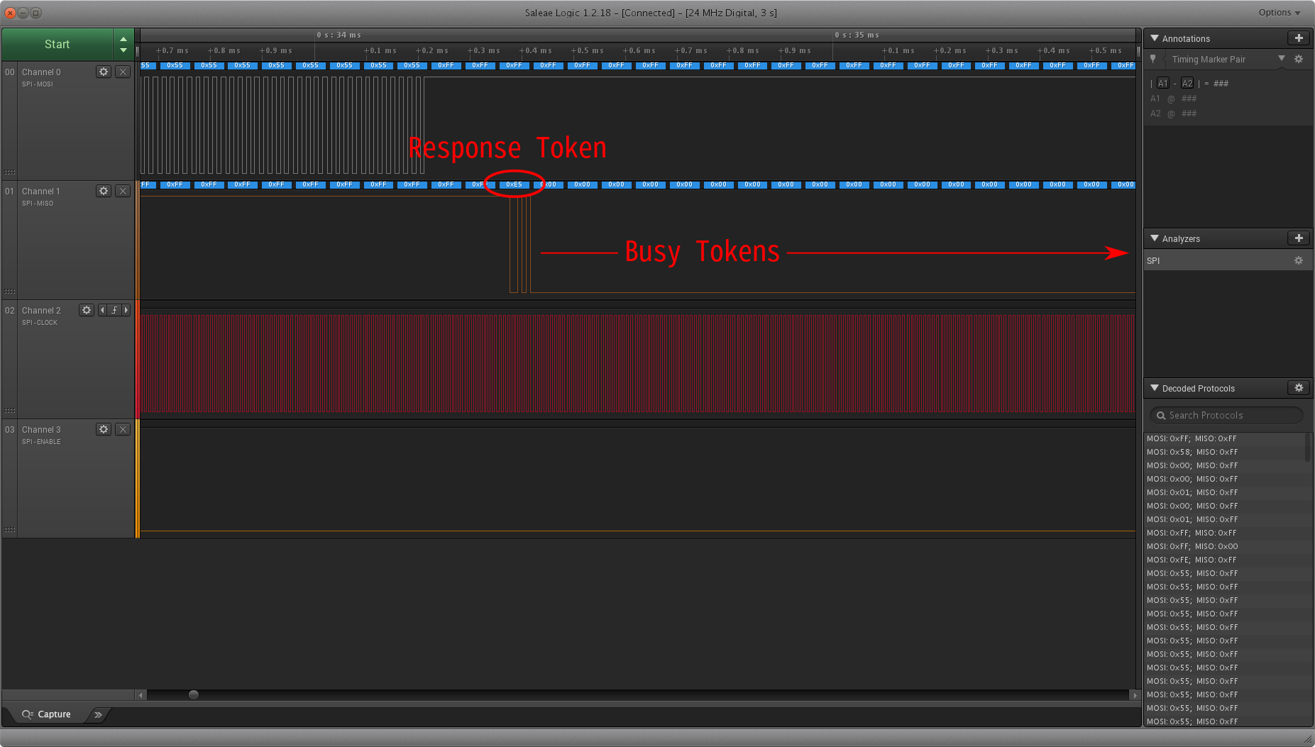
At the very end of our transmission the card sends the response token 0xE5, which is 0b11100101. The data accepted token is of the form 0bxxx00101 (where x is a don't care), so we have successfully sent the data. After that, the card sends 0x00 to indicate it's busy. In this case it took 2.7ms to finish writing the data.
Timeouts
As with read operations, we need to set a timeout value so our program does not get hung up if the card never responds. Per section 4.6.2.2 of the physical spec
Maximum length of busy is defined as 250 ms for all write operations.
As shown in the read section, I have set the maximum write attempts to (0.25s * 16000000 MHz)/(128 * 8 bytes) = 3907, which should give just over 250ms.
Note that there are 4 cases with this function that we should check after we call it:
- R1 != 0x00 → Error writing block (parse R1 for details)
- R1 == 0x00 and token == 0x05 → Success
- R1 == 0x00 and token == 0x00 → Busy Signal timeout
- R1 == 0x00 and token == 0xFF → No response after R1
Based on these combinations, we know whether the write was successful or if we need to try again.
Conclusion
There you have it. Completing this final step we now have robust functions to read and write blocks of data to an SD card. Download the source code for this tutorial here.