AVR Atmega328P UART
The Universal Asynchronous Receiver and Transmitter (UART) capability of the Atmega328P allows you to easily comminicate with your microcontroller from your PC. In addition, it is the primary interface to many other devices, such as GPS receivers. Here we will look at some basic functions that will allow you to utilize UART in your microcontroller project.
Initializing UART
There are several parameters that need to be configured to initialize UART. The first thing to decide is the baudrate. For UART, baudrate is the rate in bits per second that will be transmitted. There are a number of standard rates:
- 1200
- 2400
- 4800
- 9600
- 19200
- 38400
- 57600
- 115200
For most microcontroller projects where speed is not a huge concern (or for general debugging), 9600 is used. This equates to a maximum of 1200 characters being sent every second. However, with a 16MHz clock, the ATmega328P can go up to speeds of 1Mbps - 125000 characters every second.
Setting Baud Rate
Setting the baud rate is done by writing to the UBRR0H and UBRR0L registers. The value written is not the baud rate, however. It is given by the formula
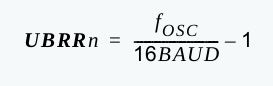
Where fOSC is your clock rate. Assuming you are using a 16MHz external oscillator for your project and have a desired baud rate of 9600, the calculation of UBRRn would yield (16000000/(16*9600)) - 1 = 103.167. Since this is not a whole number, we have to round, which yields 103. Because of this rounding, we will be transmitting and receiving at a rate slightly off of 9600. However, according to the datasheet, the clock difference will only be 0.3%, which should not give us any trouble. This is because UART receivers/transmitter synchronize on every frame, and with only 8 data bits and a few extra overhead bits in each frame, we will not drift out of the slots for each bit. (For more information on baud rate errors, check out the link here.)
Since the baud rate registers are 8 bits each, we need to separate 103 into its lower and higher byte. Since it is less than 255, it is obvious that the upper byte is 0 and the lower byte is just 103, however, a programmatic way to separate the lower and higher bytes is shown below:
    // write to lower byte
    UBRR0L = (uint8_t)(103 & 0xFF);

    // write to higher byte
    UBRR0H = (uint8_t)(103 >> 8)
In the code above, we obtain the lower byte of 103 by masking it with 0xFF and the upper byte by shifting it down by 8.
Enabling the transmitter and receiver
Next, the UART transmitter and receiver functions must be enabled. Otherwise, the UART rx/tx pins on the microcontroller will behave as standard I/O pins. To do this, we need to set the RXEN0 and TXEN0 bits to 1 in the UCSR0B register.
    // enable the transmitter and receiver
    UCSR0B |= (1 << RXEN0) | (1 << TXEN0)
Frame Format
The last thing to set it the frame format, which includes the number of data bits, number of stop bits, and the use of parity bits. By default, the system initializes with 8 data bits, no parity bits, and 1 stop bit, often abbreviated as 8N1. This is a very common format and is the default for many terminals, so we will not change it here.
Writing an initialization function
Based on everything we have seen before, here is a simple initialization function that brings all of it together.
void UART_init(uint16_t ubrr)
{
    // set baudrate in UBRR
    UBRR0L = (uint8_t)(ubrr & 0xFF);
    UBRR0H = (uint8_t)(ubrr >> 8);

    // enable the transmitter and receiver
    UCSR0B |= (1 << RXEN0) | (1 << TXEN0);
}
This initialization function must be called before using any of the UART functions or they will not work.
Transmitting a Character
The basis for all of our transmitting functions here begins with sending a single character over UART. Here is an example of a transmit character function taken from the datasheet.
void UART_putc(unsigned char data)
{
    // wait for transmit buffer to be empty
    while(!(UCSR0A & (1 >> UDRE0)));

    // load data into transmit register
    UDR0 = data;
}
In order to transmit data, we must make sure the transmit buffer is empty. According to the datasheet "If UDREn is one, the buffer is empty, and therefore ready to be written." UDRE0 is in the USART Control and Status Register 0 A (UCSR0A), and its value can be obtained by masking UCSR0A with (1 >> UDRE0). We are waiting for this value to be 1, so we set our while loop to continue as long as it is zero by negating it with the '!' operator.
When the buffer is empty, we simply load the character we want to transmit into the UDR0 register and the hardware will take care of the rest.
Transmitting a String
With a transmit character function in place, writing a function to send a string is trivial. Here is an example:
void UART_puts(char* s)
{
    // transmit character until NULL is reached
    while(*s > 0) UART_putc(*s++);
}
This compact function takes a string as an input and sends out each character one by one until it comes across a NULL. Note: This function will result in unpredictable behavior if a non NULL terminate string is passed to it.
Transmitting Hex Values
In order to transmit hex values in a format that is readable from a terminal, we need to convert them to ASCII first. This is fairly straightforward as the upper 4 bits (upper nibble) of a byte will be the first character and the lower 4 bits (lower nibble) will be the second character. Here is an example:
void UART_puthex8(uint8_t val)
{
    // extract upper and lower nibbles from input value
    uint8_t upperNibble = (val & 0xF0) >> 4;
    uint8_t lowerNibble = val & 0x0F;

    // convert nibble to its ASCII hex equivalent
    upperNibble += upperNibble > 9 ? 'A' - 10 : '0';
    lowerNibble += lowerNibble > 9 ? 'A' - 10 : '0';

    // print the characters
    UART_putc(upperNibble);
    UART_putc(lowerNibble);
}
Here we extract the upper and lower nibble simply by masking them with 0x0F (and shifting down for the upper nibble):
    // extract upper and lower nibbles from input value
    uint8_t upperNibble = (val & 0xF0) >> 4;
    uint8_t lowerNibble = val & 0x0F;
Next, we convert each nibble to its equivalent hex representation in ASCII. If the nibble is less than 10, it will be displayed as a digit. Thus, we simply add its value to the ASCII character '0' for the conversion. For example, if a nibble was equal to 5, since ASCII '0' is 48 in decimal, we would get 53, which is '5' in ASCII. If a nibble is greater than 9, then it will be represented by a letter (A, B, C, etc). The same principle as before is used, we add the value of the nibble to the lowest character, 'A'. However, the nibble 10 would need to convert to A, so we must subtract 10 from our nibble to get the correct result (i.e. subtract 10 to determine how many digits past 10 we need to go). For example, observe that (15 - 10) + 'A' = 5 + 65 = 70 = 'F'.
    // convert nibble to its ASCII hex equivalent
    upperNibble += upperNibble > 9 ? 'A' - 10 : '0';
    lowerNibble += lowerNibble > 9 ? 'A' - 10 : '0';
With an 8 bit function in place, the concept can easily be extended for larger hex values. For example, a 16 bit function would look like:
void UART_puthex16(uint16_t val)
{
    // transmit upper 8 bits
    UART_puthex8((uint8_t)(val >> 8));

    // transmit lower 8 bits
    UART_puthex8((uint8_t)(val & 0x00FF));
}
Transmitting Decimal Values
Transmitting decimal values is a little bit more tricky than hex, since we cannot just split a byte into upper and lower nibbles and convert directly. A traditional method for obtaining, say the digit in the 100s place of a value, is to obtain the quotient after dividing it by 100. However, the Atmega328P does not have a hardware divider which makes division a very costly operation. Instead, we can speed it up by replacing divide operations with subtraction. This is shown below:
void UART_putU8(uint8_t val)
{
    uint8_t dig1 = '0', dig2 = '0';

    // count value in 100s place
    while(val >= 100)
    {
        val -= 100;
        dig1++;
    }

    // count value in 10s place
    while(val >= 10)
    {
        val -= 10;
        dig2++;
    }

    // print first digit (or ignore leading zeros)
    if(dig1 != '0') UART_putc(dig1);

    // print second digit (or ignore leading zeros)
    if((dig1 != '0') || (dig2 != '0')) UART_putc(dig2);

    // print final digit
    UART_putc(val + '0');
}
The above function prints unsigned values, but what if we need signed? The solution is very simple. We just check for a negative number (MSB set to 1), in which case we print a minus sign, then call our previous function, UART_putU8 on the magnitude of our signed value.
void UART_putS8(int8_t val)
{
    // check for negative number
    if(val & 0x80)
    {
        // print negative sign
        UART_putc('-');

        // get unsigned magnitude
        val = ~(val - 1);
    }

    // print magnitude
    UART_putU8((uint8_t)val);
}
Extending this concept to larger types is simple. For example, in 16-bit:
void UART_putU16(uint16_t val)
{
    uint8_t dig1 = '0', dig2 = '0', dig3 = '0', dig4 = '0';

    // count value in 10000s place
    while(val >= 10000)
    {
        val -= 10000;
        dig1++;
    }

    // count value in 1000s place
    while(val >= 1000)
    {
        val -= 1000;
        dig2++;
    }

    // count value in 100s place
    while(val >= 100)
    {
        val -= 100;
        dig3++;
    }

    // count value in 10s place
    while(val >= 10)
    {
        val -= 10;
        dig4++;
    }

    // was previous value printed?
    uint8_t prevPrinted = 0;

    // print first digit (or ignore leading zeros)
    if(dig1 != '0') {UART_putc(dig1); prevPrinted = 1;}

    // print second digit (or ignore leading zeros)
    if(prevPrinted || (dig2 != '0')) {UART_putc(dig2); prevPrinted = 1;}

    // print third digit (or ignore leading zeros)
    if(prevPrinted || (dig3 != '0')) {UART_putc(dig3); prevPrinted = 1;}

    // print third digit (or ignore leading zeros)
    if(prevPrinted || (dig4 != '0')) {UART_putc(dig4); prevPrinted = 1;}

    // print final digit
    UART_putc(val + '0');
}
The corresponding signed function would be:
void UART_putS16(int16_t val)
{
    // check for negative number
    if(val & 0x8000)
    {
        // print minus sign
        UART_putc('-');

        // convert to unsigned magnitude
        val = ~(val - 1);
    }

    // print unsigned magnitude
    UART_putU16((uint16_t) val);
}
Receiving over UART
Receiving characters over UART is very similar to transmitting them. In this case, we just need to poll the UCSR0A register until the RXC0 bit is set. Then, we can return the received character from UDR0.
void UART_getc(void)
{
    // wait for data
    while(!(UCSR0A & (1 << RXC0)));

    // return data
    return UDR0;
}
In some cases, it does not make sense to continuously poll for characters. In that case, it is better to use interrupts. Please see my tutorial here for more information.
Get Line Function
Often, we would like to receive an entire line of data followed by a carriage return. Here is how a getline function could be written:
void UART_getLine(char* buf, uint8_t n)
{
    uint8_t bufIdx = 0;
    char c;

    // while received character is not carriage return
    // and end of buffer has not been reached
    do
    {
        // receive character
        c = UART_getc();

        // store character in buffer
        buf[bufIdx++] = c;
    }
    while((bufIdx < n) && (c != '\r'));

    // ensure buffer is null terminated
    buf[bufIdx] = 0;
}
Unlike the previous functions, here we must actually allocate a buffer to store characters in and pass it to our receive function. A main function using this might look like:
    // allocate buffer
    uint8_t bufSize = 20;
    char buf[bufSize];

    // get line from UART
    UART_getLine(buf, bufSize);

    // echo input
    UART_puts("You entered: ");
    UART_puts(buf);
    UART_putc('\n');
Source Code
A source file containing all of the above functions can be downloaded from here.