Initializing an SD Card
In this tutorial, we will go through the basics of initializing an SD card using an ATmega328P in Serial Peripheral Iterface (SPI) mode. If you are unfamiliar with SPI, please review my tutorial on the topic here. Although I am using an ATmega328P for this example, the concepts extend to any AVR microcontroller.
Much of the information I am presenting here comes directly from the SD Card Physical Specification, a copy of which can be found here.
Connections
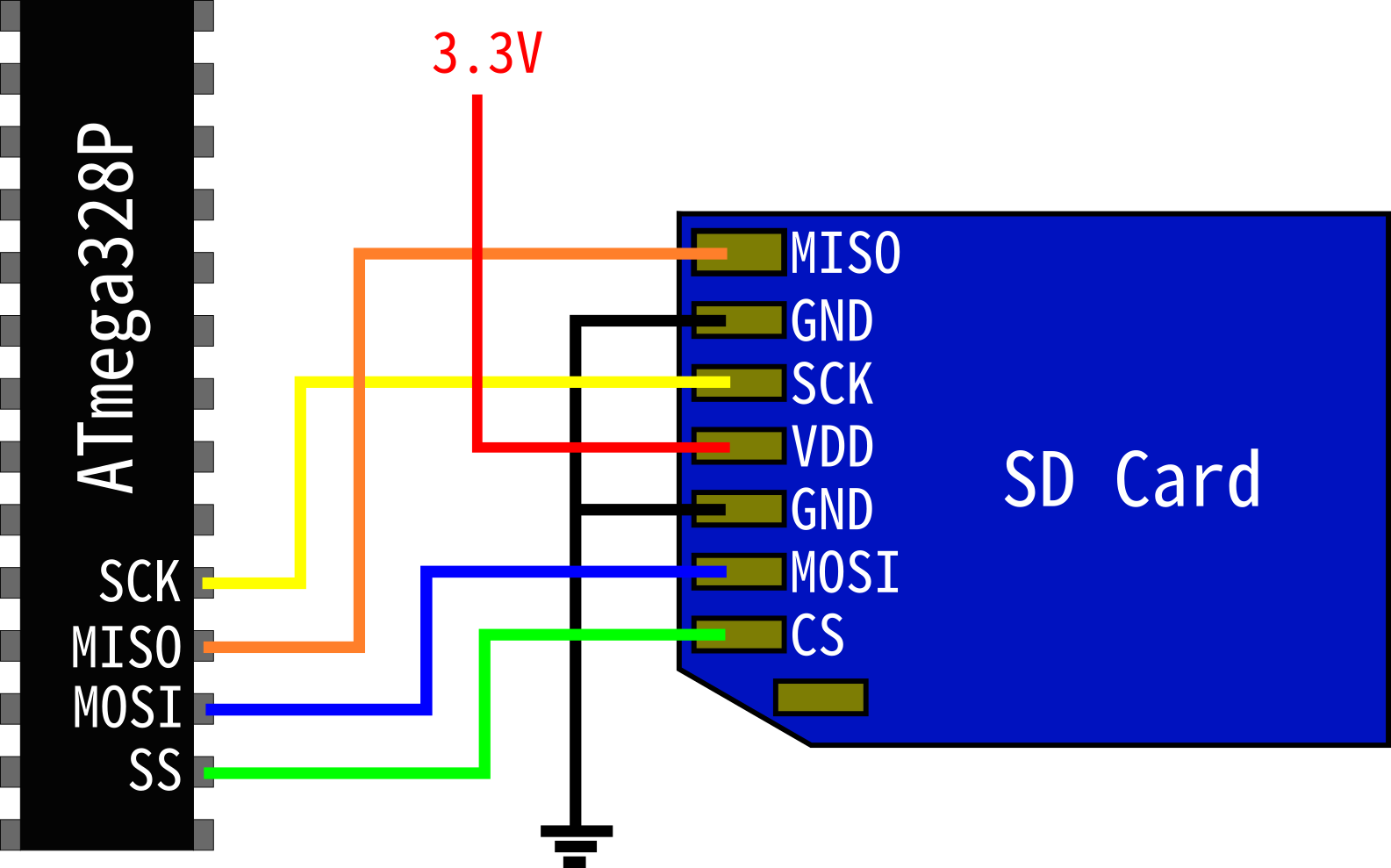
A simplified schematic is shown below for the connections between an ATmega328P and an SD card. Note that the SD card requires 3.3V power, do not connect to 5V! Also, I am using PINB2 as the Chip Select. If you choose to use a different pin you will need to modify the code presented in this tutorial.
Initializing SPI
In order to setup SPI, we need to setup a few things, namely the clock polarity, phase, and rate. Unfortunately, bus timing diagrams are not available in the simplified (free) versions of the SD Physical Layer specification. However, in this SanDisk SD Card product manual, a timing diagram is provided for one of their cards, shown below.
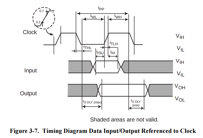
As can be seen, the clock idles low and the output is sampled on the leading edge, which corresponds to CPOL = 0 and CPHA = 0. We can assume that this mode of operation should work for other SD Cards.
CPOL and CPHA are default set to 00 in the SPCR (SPI Control Register), so we do not need to do anything with them in SPI initialization. Although modern SD Cards can operate at very high speeds, here we will set SCK to the lowest value for debugging purposes, and increase it later when we have our code working.
To abstract the pins used in our code, it will be helpful to give them functional names. Additionally, all SPI commands to the SD card require our microcontroller to first assert the Chip Select line, which means pulling it low. When we are done, we will need to return the Chip Select to a high state. Such simple commands do not necessarily warrant a function, but some simple preprocessor macros will be very helpful.
Here is our SPI initialization code, as well as our send/receive function, and some useful pin definitions and macros.
// pin definitions
#define DDR_SPI         DDRB
#define PORT_SPI        PORTB
#define CS              PINB2
#define MOSI            PINB3
#define MISO            PINB4
#define SCK             PINB5

// macros
#define CS_ENABLE()     PORT_SPI &= ~(1 << CS)
#define CS_DISABLE()    PORT_SPI |= (1 << CS)

void SPI_init()
{
    // set CS, MOSI and SCK to output
    DDR_SPI |= (1 << CS) | (1 << MOSI) | (1 << SCK);

    // enable pull up resistor in MISO
    DDR_SPI |= (1 << MISO);

    // enable SPI, set as master, and clock to fosc/128
    SPCR = (1 << SPE) | (1 << MSTR) | (1 << SPR1) | (1 << SPR0);
}

uint8_t SPI_transfer(uint8_t data)
{
    // load data into register
    SPDR = data;

    // Wait for transmission complete
    while(!(SPSR & (1 << SPIF)));

    // return SPDR
    return SPDR;
}
Power Up Sequence
The power up sequence from the physical spec is shown below.
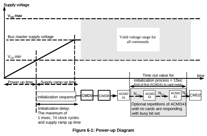
Note that we need to provide at least 1 msec delay and 74 clock cycles before sending commands to an SD Card. Since we get 8 clock cycles with each byte, we can send 10 bytes for a total of 80 clock cycles. In the notes of this section, the spec also specifies that CS must be held high during this period.
#include<util/delay.h>

void SD_powerUpSeq()
{
    // make sure card is deselected
    CS_DISABLE();

    // give SD card time to power up
    _delay_ms(1);

    // send 80 clock cycles to synchronize
    for(uint8_t i = 0; i < 10; i++)
        SPI_transfer(0xFF);

    // deselect SD card
    CS_DISABLE();
    SPI_transfer(0xFF);
}
Sending Commands
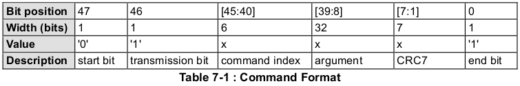
Below is the command format for SD card commands. All commands are 6 bytes long and contain a command index, arguments, and CRC. The command index field is used to tell the SD card which command you are sending. For example, if CMD0 is required, then the 6 bits in command index should be set to 000000b. The argument field is used in some commands and is ignored by the SD card in others. Whenever no arguments are needed, we will fill this field with all zeros. Finally, the Cyclic Redundancy Check (CRC) is used to ensure the contents of the command have been correctly received by the SD card. As we will see, in SPI mode, only a few commands actually require a correct CRC. In the cases where it is not needed, we will set it to all zeros.
Here we will write a function to send commands to an SD card. We will pass an 8-bit command index, a 32-bit argument, and an 8-bit CRC.
void SD_command(uint8_t cmd, uint32_t arg, uint8_t crc)
{
    // transmit command to sd card
    SPI_transfer(cmd|0x40);

    // transmit argument
    SPI_transfer((uint8_t)(arg >> 24));
    SPI_transfer((uint8_t)(arg >> 16));
    SPI_transfer((uint8_t)(arg >> 8));
    SPI_transfer((uint8_t)(arg));

    // transmit crc
    SPI_transfer(crc|0x01);
}
We begin by transmitting the command index. Note however in the command format table, that the command index is only 6 bits long. The 2 most significant bits of the command always set to 01b. If we always pass command indices less than 128 (which we will see is the case), then bit 48 of our 'cmd' argument will always be zero. However, in order to set bit 47 to 1, we need to bitwise OR our input 'cmd' with 0x40.
    // transmit command to sd card
    SPI_transfer(cmd|0x40);
Next, we transmit our 4 byte argument, one byte at a time, by shifting it down 8 bits at a time.
    // transmit argument
    SPI_transfer((uint8_t)(arg >> 24));
    SPI_transfer((uint8_t)(arg >> 16));
    SPI_transfer((uint8_t)(arg >> 8));
    SPI_transfer((uint8_t)(arg));
Finally, we transmit the CRC. Note that the CRC is only 7 bits long, and the final bit of any command is always set to 1. To make our lives easier, we will bitwise OR the 'crc' argument with 0x01 so the final bit is always 1 and we don't have to worry about it when supplying arguments to the function.
    // transmit crc
    SPI_transfer(crc|0x01);
Initialization Flow
The SPI mode initialization flow for an SD card is shown in the diagram below
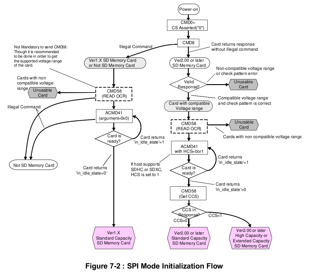
The first step in the process is to send CMD0. Below is the description of CMD0 from the physical spec.

This command is used a software reset for the SD card. Its argument is 'stuff bits', which means it will be ignored by the SD card, and the response is of type R1 (more on that later).
SPI mode is a secondary mode of communication for SD cards - they power up in an "SD Bus protocol mode." Cards only switch to SPI when the Chip Select line is driven low and CMD0 is sent. In SPI mode CRCs are ignored by default, but in SD Bus mode, which we are coming from at startup, they are required. So for the first command we must have a correct checksum.
We specify CMD0 simply by setting 'command index' to 0 in our command, and since the argument is just stuff, we will set it to 0x00000000. Now we need the CRC that corresponds to these bits. Luckily, the physical spec provides us this 7 bit value on page 43 - 10010100b. To pass this to our function, we need an 8-bit value. We can put a 0 on the end (0x94) or a 1 (0x95) but it does not matter as our function will always the final bit will always be set to 1 before we transmit.
#define CMD0        0
#define CMD0_ARG    0x00000000
#define CMD0_CRC    0x94

// send CMD0
SD_command(CMD0, CMD0_ARG, CMD0_CRC);
Note that CMD0 returns a response of format R1. The R1 format is shown below from the physical spec.
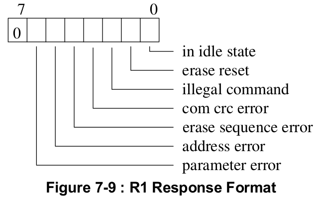
Note that R1 is a single byte, where the first bit is always 0, and every other bit represents an error condition.
Knowing this, we can write a function to retrieve a single byte response after sending CMD0. Here it is below
uint8_t SD_readRes1()
{
    uint8_t i = 0, res1;

    // keep polling until actual data received
    while((res1 = SPI_transfer(0xFF)) == 0xFF)
    {
        i++;

        // if no data received for 8 bytes, break
        if(i > 8) break;
    }

    return res1;
}
Since the MISO line is high by default, if the SD card does not respond, we will simply read 0xFF. The SD card may require some time after our command is sent to process it, so we will keep polling until we receive data. However, the card should respond within 8 cycles. If it has not responded by then we break and return the response (which will be 0xFF).
Putting all of this together, the full sequence for sending CMD0, aka GO_IDLE_STATE, is shown below
uint8_t SD_goIdleState()
{
    // assert chip select
    SPI_transfer(0xFF);
    CS_ENABLE();
    SPI_transfer(0xFF);

    // send CMD0
    SD_command(CMD0, CMD0_ARG, CMD0_CRC);

    // read response
    uint8_t res1 = SD_readRes1();

    // deassert chip select
    SPI_transfer(0xFF);
    CS_DISABLE();
    SPI_transfer(0xFF);

    return res1;
}
Here, we provide 8 clocks before and after pulling CS low, and another 8 before sending the command. This is recommended to ensure the card recognizes the change in CS. In addition, we provide and extra byte before and after transitioning CS high. These extra bytes are not always necessary but many people have had issues when multiple cards are on the bus.
Putting It All Together
Now it is time to put all of this into a program. Below is a main function using the functions defined previously in this tutorial. Here we simply go through the power up sequence and command the card to idle. Download the source code here
int main(void)
{
    // initialize SPI
    SPI_init();

    // start power up sequence
    SD_powerUpSeq();

    // command card to idle
    SD_goIdleState();

    while(1);
}
Using a logic analyzer, here is what we see when we run the program (click to go full screen).
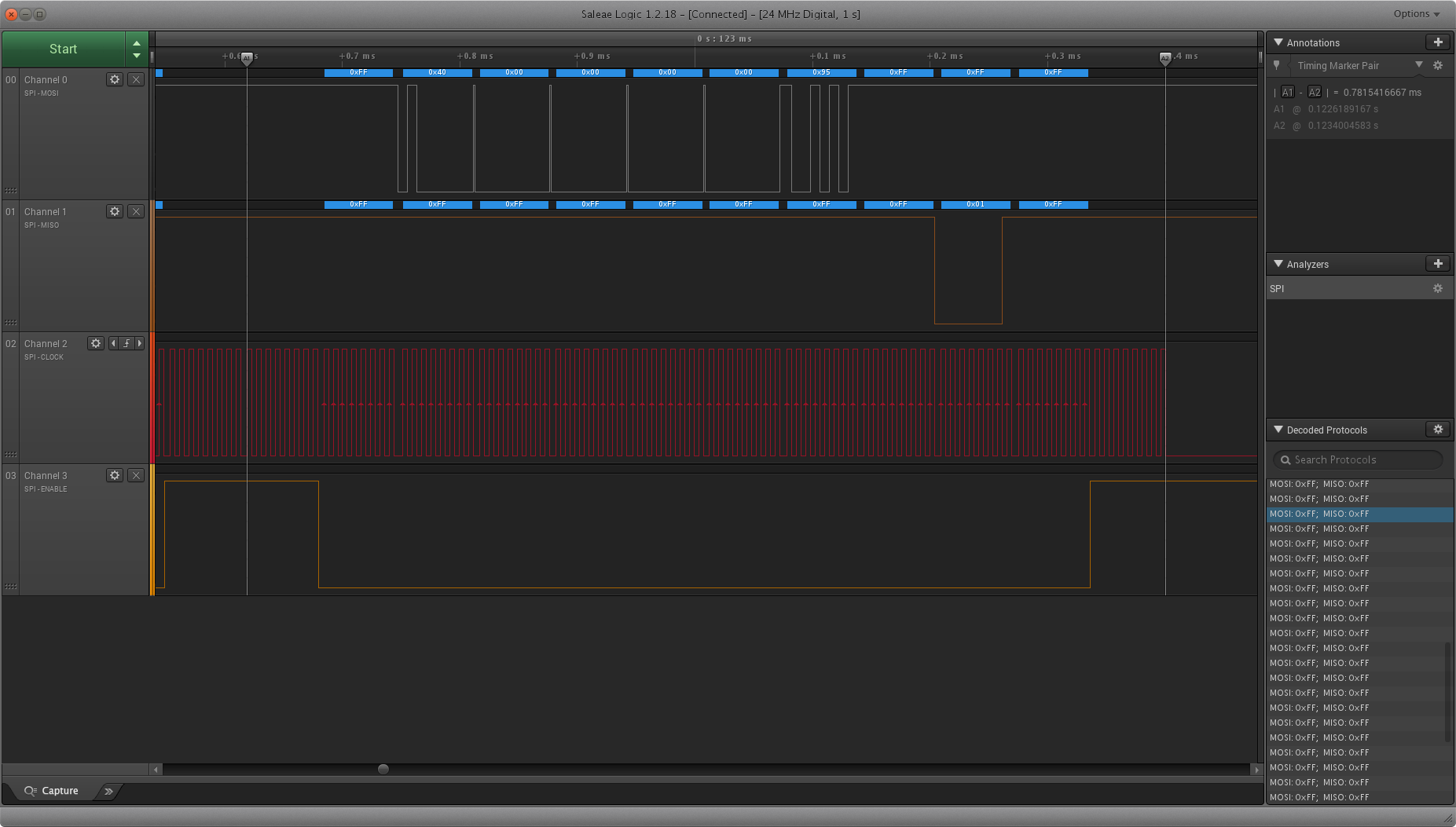
We see that the first byte transmitted is 0x40 (which is CMD0|0x40), our arguments are all 0, and our final byte is 0x95 (CMD0_CRC|0x01). Notice that it takes the SD card 8 clock cycles after sending the command to respond. Once it does, it sends 0x01. Checking back to our definition of R1, we see that that means the card is in idle state (and has no errors), which is exactly what we commanded it to do!
Click here to go onto part 2.