Initializing an SD Card Part 2
In the previous tutorial, we used CMD0 to send a card to idle state. Here we will continue the initialization process. The next step requires sending CMD8.
Command 8
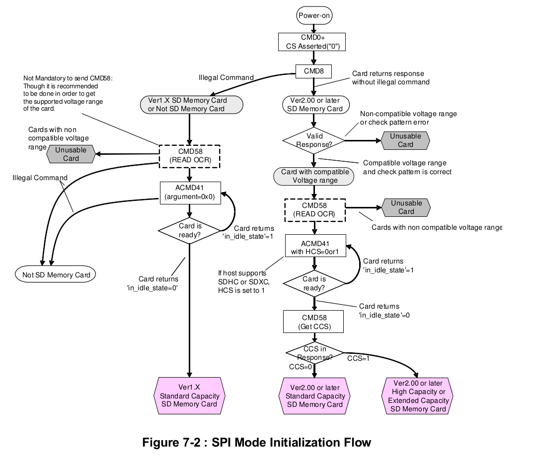
CMD8, SEND_IF_COND (send interface condition), is used to check whether the card is first generation or Version 2.00 (or later). If the card is of first generation, it will respond with R1 with bit 2 set (illegal command). This necessitates going down the left path in the initialization diagram. If the card does not indicate an illegal command we will go through the Version 2.00 path. In this tutorial, I am using Version 2.00 cards and will go through the sequence for them, although this tutorial should give you enough information to go through the other path.
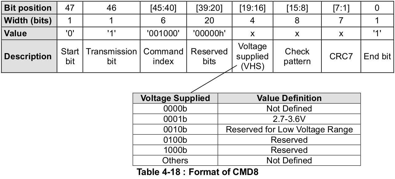
In order to send CMD8, we will set command index to 8 (001000b). Since we are operating at 3.3V, we will set VHS to 0001b. The check pattern is an arbitrary string of bits that we can set to any value, which the SD card will return in the response to ensure the command was processed correctly. Per page 40 of the version 2.00 physical spec, the recommended pattern is ‘10101010b’ (this recommendation is curiously missing from later revisions). Finally we need to set a CRC. CMD8 is the only command other than CMD0 that requires a correct CRC. Using the recommended check pattern, 3.3V VHS and setting all other bits as mandated in the command, the correct CRC is 1000011b. Thus, we can use the following to send this command:
#define CMD8        8
#define CMD8_ARG    0x0000001AA
#define CMD8_CRC    0x86 //(1000011 << 1)

// send CMD8
SD_command(CMD8, CMD8_ARG, CMD8_CRC);
R7 Response
The response to CMD8 is format R7, which is shown below.
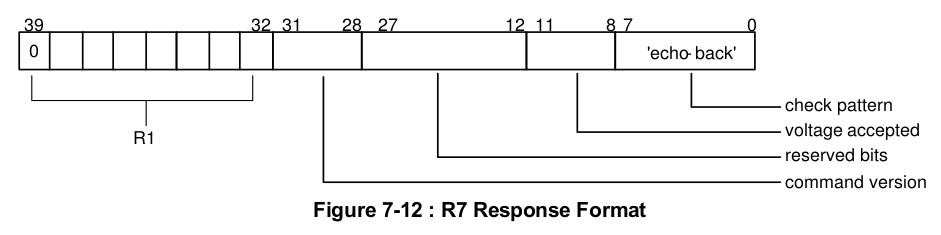
Note that R7 is 5 bytes long, and the first byte is identical to R1, which we have already seen. Following that we have a command version field, a voltage accepted field, and an "echo-back" of the check pattern we sent in the command. Note that if you are using a first generation card, it will only return R1 with the illegal bit command set.
Knowing this, we can write a function to receive R7.
void SD_readRes7(uint8_t *res)
{
    // read response 1 in R7
    res[0] = SD_readRes1();

    // if error reading R1, return
    if(res[0] > 1) return;

    // read remaining bytes
    res[1] = SPI_transfer(0xFF);
    res[2] = SPI_transfer(0xFF);
    res[3] = SPI_transfer(0xFF);
    res[4] = SPI_transfer(0xFF);
}
Note that we make use of the SD_readRes1 function we wrote in the previous tutorial and return if there are any errors (i.e. if R1 does not equal 0x01 or 0x00).
Command 8 Function
Let's pull everything we've written so far into a function to send command 8 and read the response.
void SD_sendIfCond(uint8_t *res)
{
    // assert chip select
    SPI_transfer(0xFF);
    CS_ENABLE();
    SPI_transfer(0xFF);

    // send CMD8
    SD_command(CMD8, CMD8_ARG, CMD8_CRC);

    // read response
    SD_readRes7(res);

    // deassert chip select
    SPI_transfer(0xFF);
    CS_DISABLE();
    SPI_transfer(0xFF);
}
Here we just need pass a pointer to a uint8_t array large enough to hold the entire response (5 bytes).
Printing Outputs
So we don't have to use the logic analyzer to see what the SD card is doing, we should add some UART outputs. For the rest of this tutorial I will be making use of the functions from my UART tutorial here.
First, a function to print R1.
#define PARAM_ERROR(X)      X & 0b01000000
#define ADDR_ERROR(X)       X & 0b00100000
#define ERASE_SEQ_ERROR(X)  X & 0b00010000
#define CRC_ERROR(X)        X & 0b00001000
#define ILLEGAL_CMD(X)      X & 0b00000100
#define ERASE_RESET(X)      X & 0b00000010
#define IN_IDLE(X)          X & 0b00000001

void SD_printR1(uint8_t res)
{
    if(res & 0b10000000)
        { UART_puts("\tError: MSB = 1\r\n"); return; }
    if(res == 0)
        { UART_puts("\tCard Ready\r\n"); return; }
    if(PARAM_ERROR(res))
        UART_puts("\tParameter Error\r\n");
    if(ADDR_ERROR(res))
        UART_puts("\tAddress Error\r\n");
    if(ERASE_SEQ_ERROR(res))
        UART_puts("\tErase Sequence Error\r\n");
    if(CRC_ERROR(res))
        UART_puts("\tCRC Error\r\n");
    if(ILLEGAL_CMD(res))
        UART_puts("\tIllegal Command\r\n");
    if(ERASE_RESET(res))
        UART_puts("\tErase Reset Error\r\n");
    if(IN_IDLE(res))
        UART_puts("\tIn Idle State\r\n");
}
For this function, masks are defined for each bit to determine which error condition exists in the response and print out an english description. Additionally, we return immediately if the MSB is 1 (which indicates an error receiving the response) and when no flags are set, meaning the card is ready.
Next is a similar function for R7.
#define CMD_VER(X)          ((X >> 4) & 0xF0)
#define VOL_ACC(X)          (X & 0x1F)

#define VOLTAGE_ACC_27_33   0b00000001
#define VOLTAGE_ACC_LOW     0b00000010
#define VOLTAGE_ACC_RES1    0b00000100
#define VOLTAGE_ACC_RES2    0b00001000

void SD_printR7(uint8_t *res)
{
    SD_printR1(res[0]);

    if(res[0] > 1) return;

    UART_puts("\tCommand Version: ");
    UART_puthex8(CMD_VER(res[1]));
    UART_puts("\r\n");

    UART_puts("\tVoltage Accepted: ");
    if(VOL_ACC(res[3]) == VOLTAGE_ACC_27_33)
        UART_puts("2.7-3.6V\r\n");
    else if(VOL_ACC(res[3]) == VOLTAGE_ACC_LOW)
        UART_puts("LOW VOLTAGE\r\n");
    else if(VOL_ACC(res[3]) == VOLTAGE_ACC_RES1)
        UART_puts("RESERVED\r\n");
    else if(VOL_ACC(res[3]) == VOLTAGE_ACC_RES2)
        UART_puts("RESERVED\r\n");
    else
        UART_puts("NOT DEFINED\r\n");

    UART_puts("\tEcho: ");
    UART_puthex8(res[4]);
    UART_puts("\r\n");
}
Sending CMD0 and CMD8
Now we just need to send our commands to the SD card and read the response. Here is how it would look in a main function:
int main(void)
{
    // array to hold responses
    uint8_t res[5];

    // initialize UART
    UART_init(57600);

    // initialize SPI
    SPI_init();

    // start power up sequence
    SD_powerUpSeq();

    // command card to idle
    UART_puts("Sending CMD0...\r\n");
    res[0] = SD_goIdleState();
    UART_puts("Response:\r\n");
    SD_printR1(res[0]);

    // send if conditions
    UART_puts("Sending CMD8...\r\n");
    SD_sendIfCond(res);
    UART_puts("Response:\r\n");
    SD_printR7(res);

    while(1);
}
And here is our output over UART
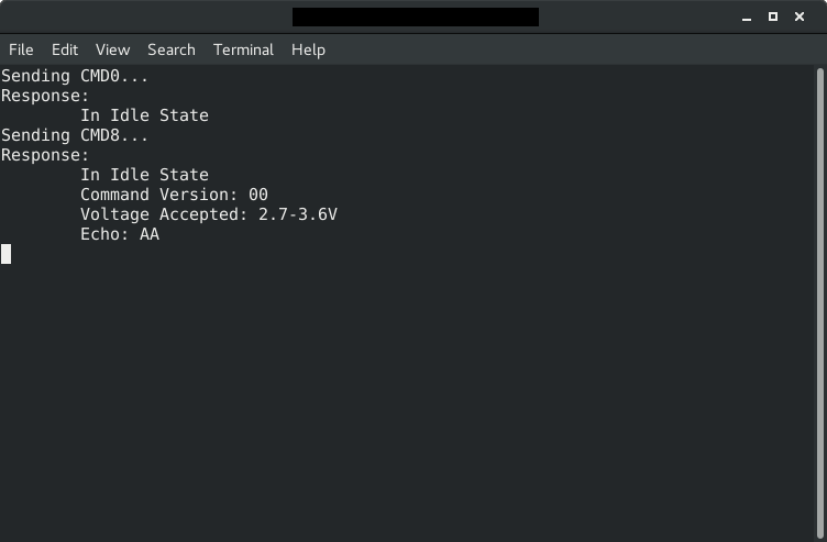
And just to make sure, here is the output for CMD8 with the logic analyzer.
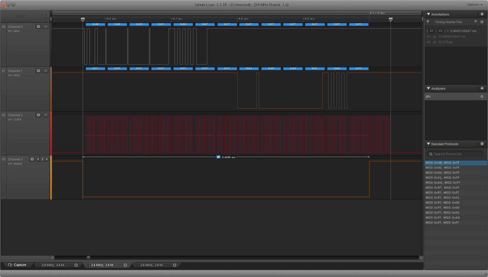
Note that the SD card did not indicate in illegal command in the first 8 bytes of R7, confirmed our voltage range (2.7-3.6V) and correctly echoed our check pattern, 0x55. Everything seems to be working!
CMD58
Now we move on to the next step, CMD58 - read OCR (operation conditions register). This command is optional at this point, but it will be required later on, so we will go ahead and look at it now.
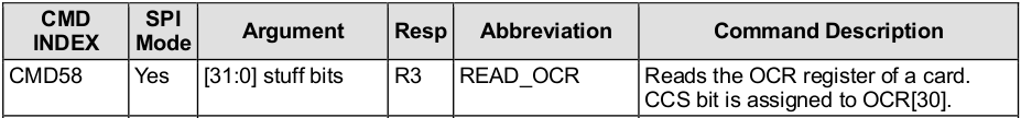
Note that the argument we supply is just 'stuff bits', and the CRC does not matter. The response format, R3, is shown below
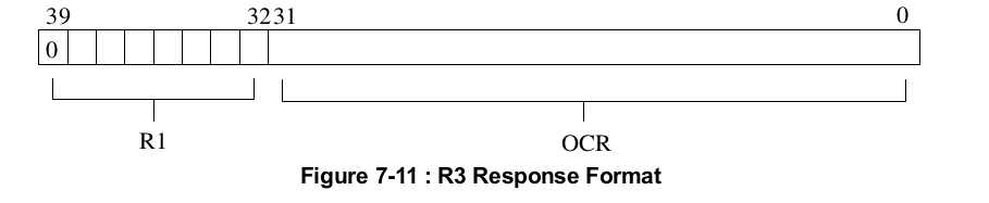
Just like with R7, the first byte is the same as R1, and the following 4 bytes are the contents of OCR, which is defined as below
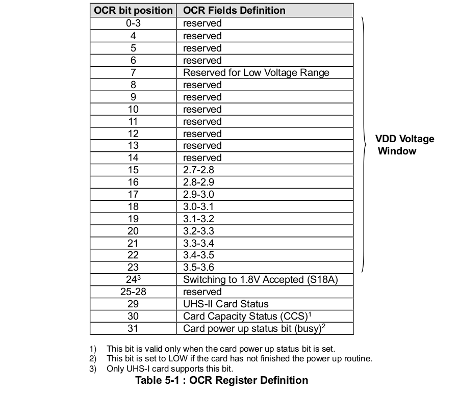
There are a few important things to note. First, each bit from 15-24 indicates a value of voltage supported by this card. Next, bit 31 is the card power up status, which is LOW if the card has not finished the power up routine. And bit 30, the card capacity status, which is only valid if the power up status is set, indicates that the card is a high capacity SD card (SDHC) or extended capacity SD card (SCXC), as opposed to a standard capacity SD card (SDSC).
Since the arguments and CRC don't matter for CMD58, we will set them all to zero.
#define CMD58       58
#define CMD58_ARG   0x00000000
#define CMD58_CRC   0x00

// send CMD58
SD_command(CMD58, CMD58_ARG, CMD_CRC);
Parsing R3
Our function for receiving R3 is the same as R7, since they are both 5 bytes long and start with R1. We can just reuse the R7 function before and rename it like below.
void SD_readRes3_7(uint8_t *res)
{
    // read R1
    res[0] = SD_readRes1();

    // if error reading R1, return
    if(res[0] > 1) return;

    // read remaining bytes
    res3[1] = SPI_transfer();
    res3[2] = SPI_transfer();
    res3[3] = SPI_transfer();
    res3[4] = SPI_transfer();
}
CMD58 Function
Putting everything we have written for CMD58 so far into a funcion
void SD_readOCR(uint8_t *res)
{
    // assert chip select
    SPI_transfer(0xFF);
    CS_ENABLE();
    SPI_transfer(0xFF);

    // send CMD58
    SD_command(CMD58, CMD58_ARG, CMD58_CRC);

    // read response
    SD_readRes3_7(res);

    // deassert chip select
    SPI_transfer(0xFF);
    CS_DISABLE();
    SPI_transfer(0xFF);
}
Printing R3 and OCR
Here is a function to print R3. As with R7, we will first check R1, and if there are any errors present skip printing the rest of the response. Following that, we print out the OCR.
#define POWER_UP_STATUS(X)  X & 0x40
#define CCS_VAL(X)          X & 0x40
#define VDD_2728(X)         X & 0b10000000
#define VDD_2829(X)         X & 0b00000001
#define VDD_2930(X)         X & 0b00000010
#define VDD_3031(X)         X & 0b00000100
#define VDD_3132(X)         X & 0b00001000
#define VDD_3233(X)         X & 0b00010000
#define VDD_3334(X)         X & 0b00100000
#define VDD_3435(X)         X & 0b01000000
#define VDD_3536(X)         X & 0b10000000

void printR3(uint8_t *res)
{
    SD_printR1(res[0]);

    if(res[0] > 1) return;

    UART_puts("\tCard Power Up Status: ");
    if(POWER_UP_STATUS(res[1]))
    {
        UART_puts("READY\r\n");
        UART_puts("\tCCS Status: ");
        if(CCS_VAL(res[1])){ UART_puts("1\r\n"); }
        else UART_puts("0\r\n");
    }
    else
    {
        UART_puts("BUSY\r\n");
    }

    UART_puts("\tVDD Window: ");
    if(VDD_2728(res[3])) UART_puts("2.7-2.8, ");
    if(VDD_2829(res[2])) UART_puts("2.8-2.9, ");
    if(VDD_2930(res[2])) UART_puts("2.9-3.0, ");
    if(VDD_3031(res[2])) UART_puts("3.0-3.1, ");
    if(VDD_3132(res[2])) UART_puts("3.1-3.2, ");
    if(VDD_3233(res[2])) UART_puts("3.2-3.3, ");
    if(VDD_3334(res[2])) UART_puts("3.3-3.4, ");
    if(VDD_3435(res[2])) UART_puts("3.4-3.5, ");
    if(VDD_3536(res[2])) UART_puts("3.5-3.6");
    UART_puts("\r\n");
}
Note that we only print CCS if the card power up status is 1, since the bit is invalid otherwise.
Creating an interactive program
One of the best ways to learn how to initialize an SD card and debug it is to create an interactive program. Here we will write a program that, depending on the character received over UART, will send a particular command to the SD card and print the response. This way you can go through each step yourself. Here is a program that, given an input 0, 1, or 2 from UART will send CMD0, CMD8, and CMD58, respectfully. Download source code here.
int main(void)
{
    uint8_t res[5];
    char c;

    // initialize UART and SPI
    UART_init(BRR);
    SPI_init();

    // give card time to power up
    _delay_ms(10);

    while(1)
    {
        // print menu
        UART_puts("MENU\r\n");
        UART_puts("------------------\r\n");
        UART_puts("0 - Send CMD0\r\n1 - Send CMD8\r\n2 - Send CMD58\r\n");
        UART_puts("------------------\r\n");

        // get character from user
        c = UART_getc();

        if(c == '0')
        {
            // send CMD0 and read response
            UART_puts("Sending CMD0...\r\n");
            CS_ENABLE();
            SD_command(CMD0, CMD0_ARG, CMD0_CRC);
            res[0] = SD_readRes1();
            CS_DISABLE();
            SPI_masterTransmit(0xFF);

            // print R1
            UART_puts("Response: \r\n");
            SD_parseR1(res[0]);
        }
        else if(c == '1')
        {
            // send CMD8 and read response
            UART_puts("Sending CMD8...\r\n");
            CS_ENABLE();
            SD_command(CMD8, CMD8_ARG, CMD8_CRC);
            SD_readRes7(res);
            CS_DISABLE();
            SPI_masterTransmit(0xFF);

            // print R7
            UART_puts("Response: \r\n");
            SD_parseR7(res);
        }
        else if(c == '2')
        {
            // send CMD58 and read response
            UART_puts("Sending CMD58...\r\n");
            CS_ENABLE();
            SD_command(CMD58, CMD58_ARG, CMD58_CRC);
            SD_readRes3(res);
            CS_DISABLE();
            SPI_masterTransmit(0xFF);

            // print R3
            UART_puts("Response: \r\n");
            SD_parseR3(res);
        }
        else
        {
            UART_puts("Unrecognized command\r\n");
        }
    }
}
Following the steps in the initialization process, you should type 0 followed by 1 then by 2, which will send CMD0, CMD8, and CMD58. Here is what it should look like:
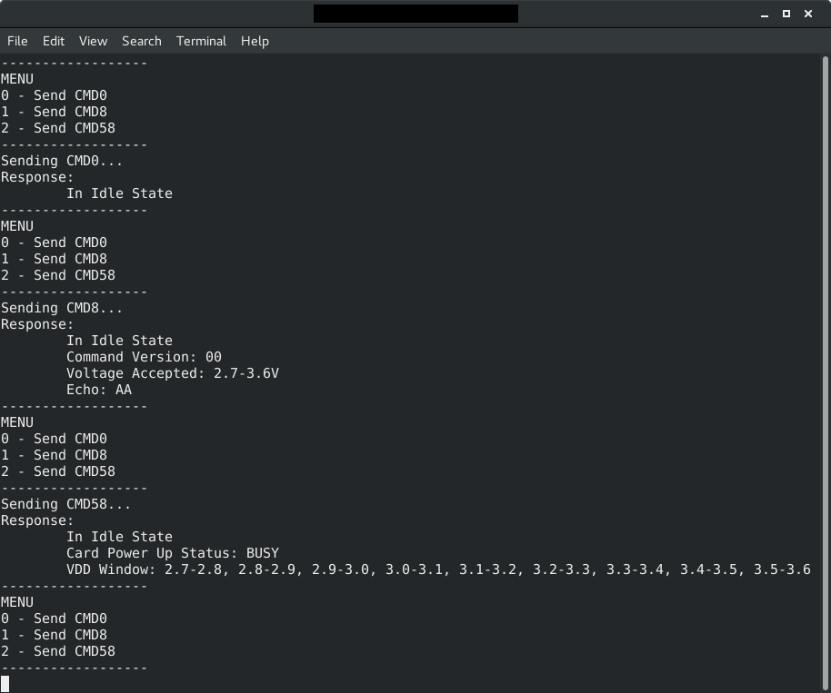
Note in the output from CMD58 the card supports all voltages between 2.7 and 3.6V and our power up status is busy (thus no CCS). At this point, if the card returned voltage values that we do not support, we would have to declare this an unusable card. Luckily, this card supports the value we are running, 3.3V, so we would continue in the initialization process.
Click here to go onto part 3.